The Arduino Uno is an open-source microcontroller board based on the MicrochipATmega328P microcontroller developed by Arduino.cc and initially released in 2010. The board is equipped with sets of digital and analog input/output (I/O) pins that may be interfaced with various expansion boards (shields) and other circuits. The board has 14 digital I/O pins (six capable of PWM output) and 6 analog I/O pins and is programmable with the Arduino IDE (Integrated Development Environment) via a type B USB cable. It can be powered by a USB cable or a barrel connector that accepts voltages between 7 and 20 volts, such as a rectangular 9-volt battery. It is similar to the Arduino Nano and Leonardo. The hardware reference design is distributed under a Creative Commons Attribution Share-Alike 2.5 license and is available on the Arduino website. Layout and production files for some versions of the hardware are also available.
The word "uno" means "one" in Italian and was chosen to mark a significant redesign of the Arduino hardware and software. The Uno board was the successor of the Duemilanove release and was the 9th version in a series of USB-based Arduino boards. Version 1.0 of the Arduino IDE for the Arduino Uno board has now evolved to newer releases. The ATmega328 on the board comes preprogrammed with a bootloader that allows uploading new code without using an external hardware programmer.
While the Uno communicates using the original STK500 protocol, it differs from all preceding boards because it does not use an FTDI USB-to-UART serial chip. Instead, it uses the Atmega16U2 (Atmega8U2 up to version R2) programmed as a USB-to-serial converter. The Arduino Uno R3 board has an In-Circuit Serial Programming (ICSP) header, which provides an interface for programming the microcontroller or communicating with other devices using SPI (Serial Peripheral Interface). The ICSP header can be used to update the firmware on the board or connect additional peripherals, such as shields or breakout boards, that rely on SPI communication.
Starting a new hardware project can be overwhelming, but the completely overhauled Copilot simplifies the process by guiding you through component selection, spec verification. Just describe your goals and Copilot engages in a focused conversation to refine your requirements like a seasoned hardware engineer.
Get help defining your project requirements, block diagram, and research components
Ask me a structured set of questions (about 5 one at a time) to help brainstorm and outline the most important parts of a project including the critical technical requirements, including power, components, performance, constraints, Use case etc
Always provide multiple options where applicable, considering trade-offs in cost, efficiency, size, and performance. By the end of this process, I want:
1. A block diagram illustrating the system architecture.
2. A complete list of all components, including passives and active components.
Go from a block diagram to specific components in a BOM
Here's a block diagram of this design. Please recommend at least three ICs from the @library for each block, highlighting their electrical characteristics and the reasons for your recommendations.
Streamline Parts Research
Instead of wading through datasheets and Google searches, use Copilot to select appropriate parts for implementation, recommending main and alternative components that meet design requirements. Tip: You can use tool like @library to direct Copilot to search the part library, or @file to direct Copilot to use datasheet details in it’s responses.
Get a list of part recommendations based on your requirements
@library List out 5 switching regulators that I can use for my project with a maximum output current of 2A. Include key parameters such as input voltage range, output voltage range, switching frequency, efficiency, and package type.
Identify alternative components for @U4 with similar functionality, pin configurations, and electrical characteristics. Include key differences and trade-offs.
@file Explain @U1 in detail, including its purpose, key functions, and common applications. Describe how it operates within a circuit and any notable characteristics. Also, explain the family or series this component belongs to, highlighting its variations, key differences, and typical use cases compared to other models in the series.
@file Extract the recommended operating conditions for @IC2. Retrieve key parameters such as supply voltage range, operating temperature range, input/output voltage levels, and other relevant conditions specified for optimal performance.
Compare LMR33630ADDAR and MP2451DJ-LF-Z in terms of efficiency, output ripple, load regulation, and thermal performance. Highlight key differences in topology, switching frequency, and suitability for a [specific application, e.g., battery-powered wearable]. Provide a recommendation based on [input voltage range, output voltage, current requirements.
Analyze all the parts in the project context and generate a consolidated parts table that optimizes component selection. Specifically, apply the following consolidation rule:
- Identify passive components (resistors, capacitors, inductors) with the same values but different MPNs (Manufacturer Part Numbers).
- Propose a single standardized MPN for each unique value, prioritizing parts with better availability, and popular supplier.
Present the table clearly. The table must strictly list and analyze all passive components in the project context. It must not use vague terms such as “etc.” or truncate the list in any way. The table should have the following headers (Original Part Category (e.g., Resistor, Capacitor, Inductor), Original Values/Specs (e.g., 10kΩ, 1μF, 100mH), Original MPNs (List all variants found in the project), Proposed Consolidated MPN (Recommended single part), Reason for Consolidation (e.g., same specs, better tolerance, reduced part diversity)
Edit Projects with Copilot
Copilot isn’t just here to answer questions—it can take direct action in your project, helping you place components, modify properties, and refine your design faster than ever. Instead of manually searching for parts or tweaking values one by one, you can ask Copilot to handle specific tasks, like adding a resistor with a defined value or updating a component’s footprint.
When Copilot detects an action it can execute, you’ll see an action button appear—click it to apply the change instantly. If you don’t see a button, try rephrasing your request or breaking it into smaller steps. While Copilot can’t yet generate an entire schematic at once, it’s great at guiding you through the process, handling tedious tasks, and keeping your workflow smooth.
When working on a design, precise calculations are key—but instead of crunching numbers manually, Copilot can help streamline the process. Whether you need to size a resistor, calculate power consumption, or verify signal integrity, you can use Copilot to gather equations and relevant data before running calculations.
Start by pulling in the necessary formulas and values using @file or @library, ensuring you have all the details upfront. Once you’ve gathered the required inputs, use the @calculator tool to perform the calculations accurately. Taking this structured approach will help you get the most reliable results from Copilot.
Using IPC standards calculate ... (e.g., trace width)
@calculator calculate the required PCB trace width for the 12V power rail according to the IPC-2221 standard. The trace should handle a current of 3A with a maximum allowable temperature rise of 10°C. Assume a copper thickness of 1oz and an ambient temperature of 25°C.
@copilot, use mermaid-formatted block diagrams to generate 2 well-detailed architecture design of this project for comparison. Make sure to use the technical and functional requirements information.
@copilot, I’m designing a custom voice-controlled speaker and I initially want it to have buttons, Bluetooth, Wi-Fi, and rechargeable battery. Help me brainstorm and develop a comprehensive product requirements document. Ask me one question at a time, waiting for my response before moving to the next question.
@copilot, validate the the suggested architecture in the block diagram matches the product requirements set for this project. Point out any missing blocks that would be needed to satisfy the requirements.
Design Circuit Blocks
Brainstorm and optimize modular circuit blocks for faster hardware development.
@copilot, here's the block diagram of this design. In a table format, recommend at least 3 IC for each block highlighting the electrical characteristics of the IC and why you recommended it.
Minimum set of components to implement the typical circuit
@copilot, list all components specified in the datasheet of U1 for building the typical application circuit. Present the information in a detailed table format with equations needed to size the components.
@copilot, outline the electrical characteristics of U4 as detailed in the datasheet. Then, suggest at least four drop-in replacement parts, presented in a table format with the columns
@copilot, query all components in the schematic that do not have an assigned manufacturer part number (MPN). Compile these components into a table format with the following details: Designator, Component Function, Electrical Properties, and Recommended MPN (Provide a list of recommended part numbers based on the component's properties, focusing on the most popular and widely available parts).
Improve Supply Chain
Focuses on optimizing component selection and management, including consolidating similar passive components and addressing part obsolescence to streamline the bill of materials and reduce costs.
@copilot, perform a BoM consolidation review to identify passive components (resistors, capacitors, and inductors) that have similar but different values (within ±50%) and the same package code. The goal is to simplify the BoM and reduce costs by replacing these components with a single value where possible, without affecting the circuit's functionality.
For each group of similar components, compare their electrical and mechanical characteristics, then identify a single value that can replace the others. Provide a detailed comparison table for each group, listing the designators, component values, package codes, and the proposed consolidated value, along with key specifications and any additional notes. Document the final proposed consolidated BoM in a table format.
@copilot, identify all components in the schematic that are either obsolete or not recommended for new designs (NRND). Compile these components into a table with the following details: Designator, Description/Function, Obsolete/NRND Status, Recommended Alternative Parts (Suggest at least 2 alternative components and their MPN that are current, widely available, and suitable replacements, based on the original component's specifications).
Calculate Component Values
Involves precise calculations for sizing various components often using Python for accuracy and presenting results in detailed tables.
@copilot, use the datasheets of LED D5 and D2 to obtain electrical characteristics needed to calculate the appropriate current-limiting resistor value. Then use python to calculate the value and present it in a well detailed table forma.
Research Components
Involves detailed examination of integrated components to ensure proper component selection and usage in the design.
@copilot, from the datasheet of U2 List the pin names, functions, and additional attributes for the IC. Include the following details for each pin in a table format: Pin Name, Function, Pin Type (e.g., power, ground, signal), Pin Direction (e.g., input, output, bidirectional, passive), Default State (e.g., high, low, floating), Voltage Level (if applicable), Additional Notes (e.g., pull-up/pull-down resistor, special considerations).
@copilot What are the absolute maximum ratings for U5? Identify any critical components that must be carefully selected to stay within these limits and present the results in a well detailed table format.
Data Visualization and Analysis
Utilizes Python to create visual representations of design data to assist in analysis and decision-making.
@copilot, list all ICs and the decoupling capacitors attached to each. Ensure to include all ICs present in the design, including digital ICs, power converters, LDOs, etc. For every IC, clearly state:
What power net the decoupling capacitors are attached to. What is the stated voltage of that net.
The voltage rating and value of the attached decoupling capacitors.
Signal with the expression “[WARNING]” if any of the following conditions are met: no decoupling capacitors are attached; the voltage of the power net is higher than the voltage rating of the capacitor; No voltage range was stated for the capacitor. Give a separate “[WARNING]” for each condition. Signal with the expression “[OK]” if none of those conditions are met
@copilot, review the design to ensure all current-limiting resistors for LEDs are correctly calculated for a current range of 1mA to 10mA. Follow these steps:
Identify all LEDs and their resistors.
Reference the datasheets for forward voltage (Vf) and current (If). Make no assumptions in this step
Calculate the correct resistor values.
Verify that schematic values match calculations.
Document findings in a table with LED designator, Vf, If, calculated resistor value, schematic value, status, and notes.
Calculates and analyzes the efficiency of PMIC in varying load conditions
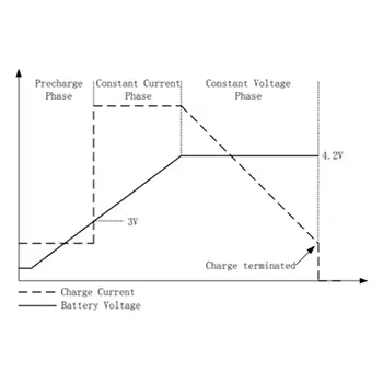
@copilot, determine the efficiency of U4 at various load conditions, considering that the input is a battery with a voltage range from 4.2V (fully charged) to 3.3V (low battery level). Identify which components in the circuit affect this efficiency and present that in a detailed table. Finally, use python to plot a graph showing the efficiency of U1 across the range of load conditions and input voltages.
Testing and Reliability Analysis
Generates test plans and collaborative workflows, ensuring your hardware is manufactured error-free.
@copilot, develop an FMEA (Failure Mode and Effects Analysis) report in a table format that analyzes the systems schematic, each unique component specification, and operational parameters. It should identify critical failure modes, assess their impact, and recommend mitigation actions based on severity, occurrence probability, and detectability. Include columns such as: process step, potential failure mode, potential failure effect, S, O, D, RPN, Action Recommended, and any other you see fit.
Initial Brainstorming
Copilot can help get you started quickly by understanding the requirements and providing guidance.
@copilot I'd like to build a smart curtain that opens or closes based on the amount of sunshine I want to enter my room. How would you approach designing this? Please ask me questions to help with the development.
@copilot can you choose 4 digital pins on the ATMega328P-AU that I have here to use as GPIO given that I am already using some pins for reset, the external clock, UART, and I2C.
Combing Through Huge Datasheets
Copilot can understand datasheets and reference them in its responses. This means you get more accurate responses when asking Copilot questions about specific parts.
Copilot answers questions about how to use Flux by referencing our documentation. So, instead of getting stuck and searching documentation, you can stay in the flow and get the help you need without leaving your project!
@copilot I want to build a PCB that uses a solar panel to charge a single cell LiPo battery. I want to measure ambient pressure with a microcontroller and send that over WiFi. What are all the components I would need?
Find Alternate Parts
Copilot can offer tailored suggestions and analyze tradeoffs based on your project goals, constraints, and specifications.
@copilot are there any alternatives to U2 that have better availability?
✨ Pro Tip: Use @tools to give Copilot more direction
Flux Copilot has a range of tools to help you through your design process. For the best results, use one tool at a time. This helps Copilot focus on a single task, making its responses more accurate and actionable.
Use @library to direct Copilot to search Flux’s library of components. This is useful when you want to insert components that are in the parts library.
Use @file when you want to direct Copilot to access datasheets, PDFs, or other documents that are attached to your project or components when conducting detailed analysis. You can also attach files to the prompt itself.
Use @calculator when you want Copilot to calculate a value with deterministic instead of relying solely on AI reasoning.
Use @code to create Python code snippets to create graphs, simulate, or validate design ideas.
Use @help to get guidance on using Flux features and best practices.
Flux Copilot is here to make hardware design more straightforward and efficient. By following these prompts and tips, you can streamline your workflow, reduce errors, and tackle each step of your project with confidence. Feel free to share your results and favorite prompts in our Slack Community.
Design a low-noise microphone preamplifier for an electret condenser mic feeding a 24-bit ADC. You must calculate the bias network, gain-setting resistors, coupling capacitors, input high-pass cutoff, output anti-aliasing RC, and decoupling layout. Follow the op-amp and microphone capsule datasheets, ADC input requirements, and industry best practices. It will be integrated into a design. Supply: 3.3V analog rail. Mic bias: 2.0 V through resistor, current ~0.5 mA. Target gain: 20 dB to 40 dB switchable. Bandwidth: 20 Hz to 20 kHz. Input noise target: as low as practical. Include pop-suppression considerations and star-grounding strategy.
The Arduino Uno is an exceptional open-source electronics platform that empowers hobbyists and professionals alike to dive into the world of embedded systems. With its user-friendly programming language, you can easily create complex projects by writing minimal code. The Uno's powerful ATmega328P microcontroller enables rapid development of innovative applications, ranging from home automation to robotics and wearable technology to environmental monitoring. What sets the Arduino Uno apart is its compatibility with an extensive array of expansion boards (shields), enabling endless customization to suit your unique project requirements. By choosing the Arduino Uno, you're investing in a platform that has proven its versatility and reliability in countless real-world applications. Don't hesitate; embrace the Arduino Uno and unlock the limitless potential of your creative genius today.
Is Arduino Uno R3 a microcontroller?
The Arduino Uno R3 is not a microcontroller itself; instead, it is a development board built around a microcontroller. The microcontroller on the Arduino Uno R3 is the ATmega328P, which is an 8-bit microcontroller from Atmel's AVR family. The board uses a USB-to-serial converter chip, which is an FTDI (Future Technology Devices International) chip on some older Arduino boards or an ATmega16U2 chip on most of the newer Arduino Uno R3 boards. The Arduino Uno R3 provides an easy-to-use platform for programming and interfacing with the ATmega328P microcontroller and various peripherals and components, making it an ideal choice for various projects.
Arduino Uno Specification
| Specification | Value |
| :=== | :=== |
| Microcontroller | ATmega328P |
| Operating Voltage | 5V |
| Input Voltage (Recommended)| 7-12V |
| Input Voltage (Limits)| 6-20V |
| Digital I/O Pins | 14(6 of which can be used as PWM outputs |
| Analog Input Pins | 6 |
| Total DC Current for I/O Pins | 200mA |
| DC Current per I/O Pin | 20mA |
| DC Current for 3.3V Pin | 50mA |
| Flash Memory | 32KB (0.5KB used by bootloader) |
| SRAM | 2KB |
| EEPROM | 1KB |
| Clock Speed | 16MHz |
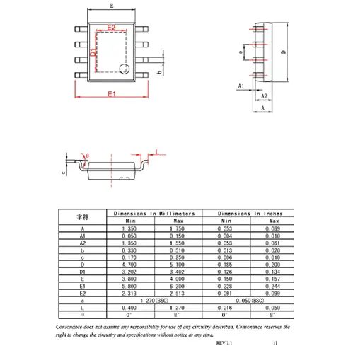
| Length | 68.6mm (2.7 inches) |
| Width | Width 53.4mm (2.1 inches) |
| Weight | 25g |
| Power Connector | 2.1mm x 5.5mm barrel jack |
| Reset Button | Yes |
| Power LED | Yes |
| TX/RX LEDs | Yes |
| LED | Yes (connected to digital pin 13) |
| Voltage Regulator | NCP1117 (5V, 1A) |
SmokeSensor Shield - Arduino Uno shield is used to monitor chimney smoke and provide feedback to the stove.
What processor is on an Arduino Uno R3?
The Arduino Uno R3 uses the ATmega328P microcontroller as its central processor. The ATmega328P is an 8-bit microcontroller from the AVR family produced by Microchip (previously Atmel). It features a 16 MHz clock speed, 32 KB of flash memory, 2 KB of SRAM, and 1 KB of EEPROM.
How fast is an Arduino Uno R3?
The Arduino Uno R3 has an ATmega328P microcontroller, which operates at a clock speed of 16 MHz. The processor can execute up to 16 million instructions per second. While this speed is relatively low compared to modern microprocessors, it is more than sufficient for most hobbyist projects and simple applications, such as sensor reading, basic automation, and simple robotics.
What is the pinout of the Arduino Uno?
| Pin No. | Pin Name | Pin Type | Description |
| :=== | :=== | :=== | :=== |
| 1 | Reset | Reset | Resets the microcontroller when pulled LOW; usually connected to the reset button |
| 2-3 | TX,RX | Serial | Digital pins 0 (RX) and 1 (TX) for serial communication |
| 4-9 | D2 - D7 | Digital I/O | General-purpose digital I/O pins |
| 10-13 | D8 - D13 | Digital I/O | General-purpose digital I/O pins (D13 has built-in LED) |
| 14-19 | A0 - A5 | Analog Input | Analog input pins can also be used as digital I/O pins |
| 20 | AREF | Reference | The external voltage reference for analog inputs |
| 21 | 3V3 | Power | 3.3V output from on-board voltage regulator (max 50mA) |
| 22 | GND | Ground | Ground pins |
| 23 | GND | Ground | Ground pins |
| 24 | VIN | Power | Power input from the external power source or connected to VCC when USB powered |
| 25 | 5V | Power | 5V output from the onboard voltage regulator |
| 26 | D10 - D11 | SPI | SPI communication pins (D10 - SS, D11 - MOSI) |
| 27-28 | D12 - D13 | SPI | SPI communication pins (D12 - MISO, D13 - SCK) |
| 29-30 | A4 - A5 | I2C | I2C communication pins (A4 - SDA, A5 - SCL) |
| 31 | D9 | PWM | Pulse Width Modulation (PWM) capable digital I/O pin |
| 32 | D10 | PWM | Pulse Width Modulation (PWM) capable digital I/O pin |
| 33 | D11 | PWM | Pulse Width Modulation (PWM) capable digital I/O pin |
| 34 | D3 | PWM/Interrupt | PWM capable digital I/O pin and external interrupt 1 (INT1) |
| 35 | D5 | PWM/Interrupt | PWM capable digital I/O pin and external interrupt 0 (INT0) |
| 36 | D6 | PWM | Pulse Width Modulation (PWM) capable digital I/O pin |
This table provides a comprehensive overview of the Arduino Uno R3's pinout, which can be helpful when planning and building projects using this development board. Note that some pins have multiple functions, such as digital I/O, analog input, PWM, and communication protocols like SPI and I2C.
Arduino Uno R3 Shield Template - Include an official pinout so you will always know Arduino names and the alternative roles of pins.
What are the 3 types of pins on Arduino?
On an Arduino board, there are three primary types of pins:
Digital I/O pins: These pins are used for digital input and output operations. They can read or produce either a HIGH (5V) or LOW (0V) signal, which is helpful for controlling devices like LEDs or reading the state of buttons. Some of these pins also support Pulse Width Modulation (PWM), allowing for the generation of analog-like signals to control devices such as servos or dimmable LEDs.
Analog input pins: Analog input pins are used to read varying voltage levels, typically between 0V and the operating voltage (5V for Arduino Uno). These pins are connected to an Analog-to-Digital Converter (ADC) inside the microcontroller, which translates the analog voltage to a digital value. Analog input pins are commonly used for reading sensor data, such as temperature, light, or pressure sensors.
Power and ground pins: These pins provide power and grounding connections for the board and connected components. The power pins include the supply voltage (5V or 3.3V, depending on the board), VIN for external power input, and sometimes a voltage reference pin (AREF). The ground pins are connected to the board's ground plane, providing a common reference point for all connected components.
In addition to these three primary types of pins, some Arduino boards also have pins supporting communication protocols like I2C, SPI, and UART for serial communication, enabling the board to interface with various peripherals and other devices.
How many ground pins are there on the Arduino Uno board?
The Arduino Uno board has a total of 5 ground pins. Three of them are located in the power section of the board, alongside the 5V, 3.3V, and VIN pins. The other two ground pins are situated beside the digital I/O pins, specifically next to pin 13 and the AREF pin. These ground pins can be used interchangeably to provide a common reference point for the connected components and circuits.
How do I program Arduino Uno R3?
To program an Arduino Uno R3, follow these steps:
Install the Arduino IDE: Download and install the Arduino Integrated Development Environment (IDE) on your computer from the official Arduino website. The IDE is available for Windows, macOS, and Linux.
Connect the Arduino Uno R3: Use a USB cable (Type A to Type B) to connect the Arduino Uno R3 to your computer.
Launch the Arduino IDE: Open the Arduino IDE software on your computer.
Select the board and port:
Go to the "Tools" menu, then "Board", and choose "Arduino Uno" from the list of available boards.
Next, go to "Tools" again, then "Port", and select the appropriate serial port that corresponds to your Arduino Uno R3. This will typically be labeled as "COM#" on Windows, "/dev/cu.usbmodem#" on macOS, or "/dev/ttyACM#" on Linux.
Write or open a sketch (program):
To create a new sketch, go to "File" > "New" and start writing your code in the editor.
To open an example sketch, go to "File" > "Examples" and choose a sketch from the list of built-in examples.
Compile and upload the sketch:
Click the checkmark icon (✓) in the top left corner of the IDE to compile the sketch and check for any errors.
If the compilation is successful, click the right arrow icon (→) next to the checkmark to upload the sketch to the Arduino Uno R3.
Monitor the output (optional):
If your sketch involves serial communication or you need to debug your code, click the magnifying glass icon in the top right corner of the IDE to open the Serial Monitor.
Ensure the baud rate in the Serial Monitor matches the one specified in your sketch (e.g., Serial.begin(9600);).
After completing these steps, your Arduino Uno R3 should be successfully programmed and running the uploaded sketch. You can now modify the sketch or experiment with different examples to explore various functionalities and applications.
Is Arduino an IDE?
Arduino refers to both a hardware platform and an Integrated Development Environment (IDE).
Hardware Platform: Arduino is a family of open-source microcontroller-based development boards designed for electronics projects and prototyping. Examples include the Arduino Uno, Arduino Mega, and Arduino Nano. These boards typically feature a variety of digital and analog input/output pins, a microcontroller (e.g., ATmega328P on the Arduino Uno), and built-in communication interfaces, such as I2C, SPI, and UART.
Integrated Development Environment (IDE): The Arduino IDE software application provides an easy-to-use environment for writing, compiling, and uploading code (called sketches) to Arduino boards. The Arduino IDE supports the Arduino programming language, which is based on C/C++ but incorporates simplified syntax and built-in functions, making it more accessible for beginners. The IDE also includes a Serial Monitor for debugging and monitoring serial communication between the Arduino board and the computer.
Is Arduino IDE similar to Python?
The Arduino IDE and Python are related in the sense that they are both software environments used for programming, but they serve different purposes and are based on different programming languages.
Arduino IDE: The Arduino Integrated Development Environment (IDE) is a software application specifically designed for programming Arduino boards. The Arduino programming language used in the IDE is based on C/C++, with simplified syntax and built-in functions to make it more accessible for beginners. The Arduino IDE provides functionalities like writing, compiling, and uploading code to Arduino boards and a Serial Monitor for debugging and monitoring serial communication.
Python: Python is a high-level, versatile programming language widely used for various applications, such as web development, data analysis, artificial intelligence, and more. It is known for its readability and ease of use, making it a popular choice among beginners and experienced developers alike. Depending on the user's preference, Python programs can be written and executed using different IDEs, text editors, or the command line.
Is Arduino IDE C or C++?
The Arduino IDE supports a programming language based on both C and C++. The Arduino programming language inherits the syntax, data types, and control structures from C/C++, but it also incorporates simplified syntax and built-in functions to make it more accessible for beginners.
When you write a sketch (program) in the Arduino IDE, you can use features from both C and C++ languages, including object-oriented programming (OOP) concepts like classes and objects from C++.
Under the hood, the Arduino IDE uses the AVR-GCC compiler (for boards based on AVR microcontrollers, such as the Arduino Uno) or other appropriate compilers for different microcontroller families. These compilers support both C and C++ languages, allowing you to fully utilize the features of both languages in your Arduino sketches.
This template is a good starting point for your Arduino based project.
What is pinMode in Arduino?
In Arduino, pinMode is a built-in function used to configure a specific digital I/O pin as either an input or an output. This function is essential for setting up the behavior of each pin on the Arduino board before using them in a sketch (program).
The pinMode function takes two arguments:
The pin number: The number of the digital I/O pin you want to configure.
The mode: The desired mode for the pin, either INPUT, OUTPUT, or INPUT_PULLUP.
Here's the syntax for using pinMode:
pinMode(pin, mode);
Typically, you call the pinMode function in the setup() section of your Arduino sketch to configure the pin behavior before the main loop starts executing.
For example, to configure digital pin 13 as an output, you would write:
void setup() { pinMode(13, OUTPUT); // Set digital pin 13 as an OUTPUT}
And to configure digital pin 2 as an input with an internal pull-up resistor, you would write:
void setup() { pinMode(2, INPUT_PULLUP); // Set digital pin 2 as an INPUT_PULLUP }
Using pinMode correctly is crucial for ensuring the proper operation of your Arduino projects and avoiding potential issues with pin configurations.
Is pinMode necessary in Arduino?
Using pinMode in Arduino is necessary when working with digital I/O pins because it configures the pin behavior as either an input or an output. Properly setting the pin mode ensures that the Arduino board can interact with connected components as intended.
What is the difference between pinMode and digitalWrite?
pinMode and digitalWrite are built-in functions in the Arduino programming language, and they serve different purposes related to digital I/O pins on an Arduino board:
pinMode: This function is used to configure a specific digital I/O pin as either an INPUT or an OUTPUT. It takes two arguments: the pin number and the mode (INPUT, OUTPUT, or INPUT_PULLUP). The pinMode function should be called in the setup() function of the Arduino sketch to configure the pin behavior before executing the main loop.
Syntax: pinMode(pin, mode);
Example:
pinMode(13, OUTPUT); // Set digital pin 13 as an OUTPUT
digitalWrite: This function is used to set the state of a digital output pin to either HIGH (5V) or LOW (0V). It takes two arguments: the pin number and the desired state (HIGH or LOW). The digitalWrite function is typically used in the loop() function or other functions to control devices like LEDs, relays, or other digital components.
Syntax: digitalWrite(pin, value);
Example:
digitalWrite(13, HIGH); // Set digital pin 13 to HIGH (5V)
In summary, the pinMode function configures a digital I/O pin as either an input or an output, while the function sets the state of a digital output pin to HIGH or LOW.
What is Arduino Uno R3 used for?
The Arduino Uno R3 is a versatile, open-source microcontroller board used for a wide range of applications, including electronics projects, prototyping, learning programming and electronics, and building interactive systems. Some common uses for the Arduino Uno R3 include:
Education: The Arduino Uno R3 is a popular choice for students and educators to learn programming and electronics concepts, thanks to its user-friendly programming environment, easy-to-interface with a breadboard, extensive online resources, and active community support.
Hobbyist projects: The Arduino Uno R3 is often used by hobbyists to create various DIY projects, such as home automation systems, robots, interactive art installations, and musical instruments.
Prototyping: The Arduino Uno R3 provides a cost-effective and accessible platform for engineers, designers, and makers to develop and test their ideas before creating custom PCBs or moving on to more advanced microcontroller boards.
Sensor interfacing: The Arduino Uno R3 can be used to interface with a wide variety of sensors, such as temperature, humidity, light, and motion sensors, allowing users to collect data and build monitoring systems for various applications.
Actuator control: The Arduino Uno R3 can control various actuators like motors, servos, relays, and solenoids, enabling the creation of automated systems, robotics, and mechatronic devices.
Communication with other devices: The Arduino Uno R3 supports communication protocols like I2C, SPI, and UART, allowing it to interface with other microcontrollers, computers, or peripherals, such as displays, EEPROMs, or wireless communication modules.
These are just a few examples of what the Arduino Uno R3 can be used for. Its simplicity, accessibility, and flexibility make it a popular choice for a wide range of applications, from beginner-level projects to more complex systems.
Share
Lance Cassidy
Lance is Co-Founder & CDO of Flux, a hardware design platform that’s revolutionizing how teams create and iterate on circuits. Find him on Flux @lwcassid
Go 10x faster from idea to PCB
Flux is an all-in-one EDA. Use re-usable blocks, scripting, and a library you don’t have to manage to dramatically reduce the time it takes to go from idea to prototype.
This blog post explores the fundamental role of diodes in electronics, focusing on understanding their symbols and various types like Zener, Schottky, and LEDs. It details the electrical signal of diodes, illustrating how they allow current flow in one direction.
Learn how smart vias in Flux automates the selection, placement, and configuration of vias during the PCB design process. This automation reduces the manual effort involved in via placement and significantly lowers the risk of misalignment and other common errors associated with traditional via management.
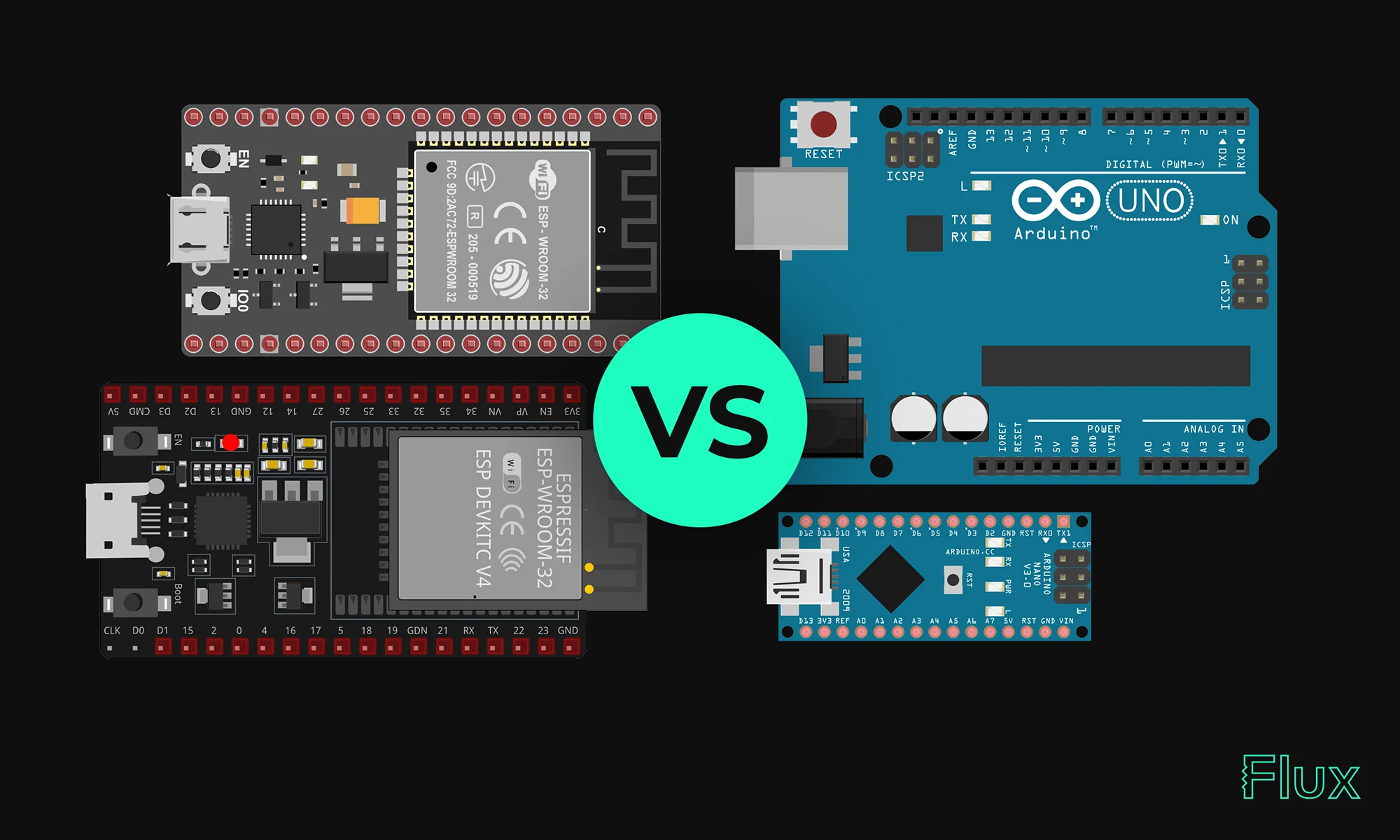
Our 2023 guide compares ESP32 and Arduino, two essential microcontrollers in IoT. ESP32 offers advanced features like Wi-Fi, while Arduino excels in ease of use and community support. Choose based on your project's complexity and needs.
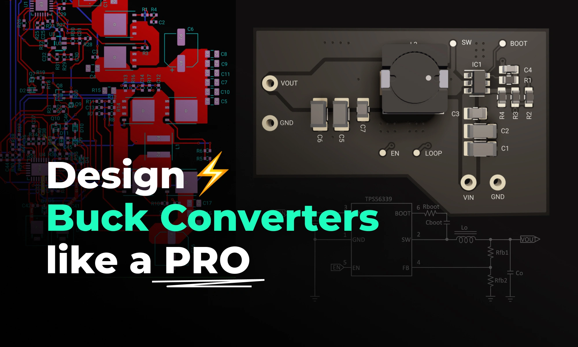
Design high-performance buck converters with proven PCB layout best practices. Cut noise, save space, and optimize your power supply design with this guide.
Delve into the essentials of circuit diagrams, exploring the various electronics symbols and their roles in design, while also offering practical advice for effective use of diagramming tools like Flux.
A comprehensive guide to using solder flux in electronics soldering. Soldering flux is used to clean and prepare the surfaces of the components that need to be joined. It helps to remove oxidation and other contaminants that can prevent a strong bond from forming. Flux also reduces surface tension, allowing the solder to flow more easily and improves the wetting of the components.
The blog post provides an in-depth look at the LM741 pinout diagram, explaining the functions of each pin, including inverting and non-inverting inputs, and comparing the LM741 to the LM324. It also covers various applications of the LM741 as an amplifier and a comparator.
Now, Flux Copilot can learn how you work—your design principles, part selection preferences, schematic style guidelines, and testing workflows—and remember them automatically.
Effortlessly calculate parallel and series resistor values with our accurate, user-friendly tool designed to optimize circuit performance and streamline electrical design processes.
Despite newer technologies like USB and Ethernet, RS232 remains widely used due to its simplicity and broad compatibility. It's crucial in industries, scientific instruments, networking gear, and legacy computers. This protocol's reliability makes it the go-to for many applications. In this blog, we'll explore why RS232 continues to be relevant in our tech-savvy world.
Explore the key aspects of PCB thermal analysis and discover best practices for enhancing your PCB design. Understand how thermal conductivity impacts heat management and overall PCB functionality, leading to more reliable and efficient circuits.