If this sounds interesting to you and you'd like to request a demo or learn more, please contact sales.
Contact Sales
USE Flux Project Requirements Template
GO TO FLUX
Try AI Auto-Layout now!
Check if you got early access
Learn more about AI Auto-Layout
Explore NextPCB Templates
Open Flux to see if you have access
Download the Full Guide
View Projects with Polygons
Open Flux and start teaching Copilot
DOWNLOAD THE PDF
Try GPT-5 in Flux now
Copy PromptGet help defining your project requirements, block diagram, and research components
Ask me a structured set of questions (about 5 one at a time) to help brainstorm and outline the most important parts of a project including the critical technical requirements, including power, components, performance, constraints, Use case etc
Always provide multiple options where applicable, considering trade-offs in cost, efficiency, size, and performance. By the end of this process, I want:
1. A block diagram illustrating the system architecture.
2. A complete list of all components, including passives and active components.
Copy PromptGo from a block diagram to specific components in a BOM
Here's a block diagram of this design. Please recommend at least three ICs from the @library for each block, highlighting their electrical characteristics and the reasons for your recommendations.
Copy PromptGet a list of part recommendations based on your requirements
@library List out 5 switching regulators that I can use for my project with a maximum output current of 2A. Include key parameters such as input voltage range, output voltage range, switching frequency, efficiency, and package type.
Copy PromptExtract reference design information from a part’s datasheet
@file extract the following details from the datasheet of @U2
1. Key features
2. Functional Pin Description
- List each pin with its name, function, and relevant electrical characteristics.
3. From the Typical Application Circuit:
- List all components present along with their values in a table format.
- Describe explicitly how each pin is connected.
4. Any circuit-Specific Design Notes
Copy PromptAlternative parts recommendations
Identify alternative components for @U4 with similar functionality, pin configurations, and electrical characteristics. Include key differences and trade-offs.
Copy PromptObtain part’s maximum ratings
@file extract the absolute maximum ratings of @U1 including voltage, current, and thermal limits. Present the data in a clear table format.
Copy PromptComponent research
@file Explain @U1 in detail, including its purpose, key functions, and common applications. Describe how it operates within a circuit and any notable characteristics. Also, explain the family or series this component belongs to, highlighting its variations, key differences, and typical use cases compared to other models in the series.
Copy PromptObtain component operating conditions
@file Extract the recommended operating conditions for @IC2. Retrieve key parameters such as supply voltage range, operating temperature range, input/output voltage levels, and other relevant conditions specified for optimal performance.
Copy PromptCompare different parts
Compare LMR33630ADDAR and MP2451DJ-LF-Z in terms of efficiency, output ripple, load regulation, and thermal performance. Highlight key differences in topology, switching frequency, and suitability for a [specific application, e.g., battery-powered wearable]. Provide a recommendation based on [input voltage range, output voltage, current requirements.
Copy PromptConsolidate the BoM
Analyze all the parts in the project context and generate a consolidated parts table that optimizes component selection. Specifically, apply the following consolidation rule:
- Identify passive components (resistors, capacitors, inductors) with the same values but different MPNs (Manufacturer Part Numbers).
- Propose a single standardized MPN for each unique value, prioritizing parts with better availability, and popular supplier.
Present the table clearly. The table must strictly list and analyze all passive components in the project context. It must not use vague terms such as “etc.” or truncate the list in any way. The table should have the following headers (Original Part Category (e.g., Resistor, Capacitor, Inductor), Original Values/Specs (e.g., 10kΩ, 1μF, 100mH), Original MPNs (List all variants found in the project), Proposed Consolidated MPN (Recommended single part), Reason for Consolidation (e.g., same specs, better tolerance, reduced part diversity)
Copy PromptAdd parts to the project
I want the 555 timer to operate at a frequency of 1.5 kHz.
@library add the following components to the project:
- NE555 Timer IC
- 2-Pin Terminal Block Connector (for power input)
- Resistors:
- R1 = 10kΩ
- R2 = 100Ω
- R3 (Current-limiting resistor for output)
- Capacitors:
- C1 = 100nF (0.1µF)
- C2 = 0.1µF (Decoupling capacitor)
- Diode: 1N4148
- LED
- Ground connection
Copy PromptAdd a part to the project
@library add the following components to this project; NE555 Timer IC, 2-Pin Terminal Block Connector (for power input) and two 0603 1k ohm resistors
Copy PromptQuick batch edits to properties
Replace all 100nF capacitors with 10nF
Copy PromptSize passives - Sizing passives happens in two steps. First obtain the equations specified in the datasheet. Then perform the calculation
@file obtain the equation for sizing the inductor for @U2, along with the required parameter values needed for the calculation.
Copy Prompt@calculator calculate the inductor size for U2 needed for my project (Vin = 5V, Vout = 3.3V, Iout = 1A)
Copy PromptUsing IPC standards calculate ... (e.g., trace width)
@calculator calculate the required PCB trace width for the 12V power rail according to the IPC-2221 standard. The trace should handle a current of 3A with a maximum allowable temperature rise of 10°C. Assume a copper thickness of 1oz and an ambient temperature of 25°C.
Copy PromptCalculate decoupling capacitance
@calculator calculate the required decoupling capacitance for @C2 and @C3 considering ±50mv noise/ripple range.
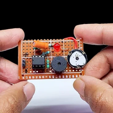
![Thumbnail of the electronic project]()
Copy PromptSee it in ActionGenerate high level block diagram
@copilot, use mermaid-formatted block diagrams to generate 2 well-detailed architecture design of this project for comparison. Make sure to use the technical and functional requirements information.
![Thumbnail of the electronic project]()
Copy PromptSee it in ActionWrite a product requirement document with AI
@copilot, I’m designing a custom voice-controlled speaker and I initially want it to have buttons, Bluetooth, Wi-Fi, and rechargeable battery. Help me brainstorm and develop a comprehensive product requirements document. Ask me one question at a time, waiting for my response before moving to the next question.
![Thumbnail of the electronic project]()
Copy PromptSee it in ActionArchitecture design review
@copilot, validate the the suggested architecture in the block diagram matches the product requirements set for this project. Point out any missing blocks that would be needed to satisfy the requirements.
![Thumbnail of the electronic project]()
Copy PromptSee it in ActionPower tree design
@copilot, based on my requirements, help me figure out the best power architecture for this project. What should the power tree look like?
![Thumbnail of the electronic project]()
Copy PromptSee it in ActionMain part recommendation
@copilot, here's the block diagram of this design. In a table format, recommend at least 3 IC for each block highlighting the electrical characteristics of the IC and why you recommended it.
![Thumbnail of the electronic project]()
Copy PromptSee it in ActionMinimum set of components to implement the typical circuit
@copilot, list all components specified in the datasheet of U1 for building the typical application circuit. Present the information in a detailed table format with equations needed to size the components.
![Thumbnail of the electronic project]()
Copy PromptSee it in ActionAlternative parts recommendation
@copilot, outline the electrical characteristics of U4 as detailed in the datasheet. Then, suggest at least four drop-in replacement parts, presented in a table format with the columns
- Replacement Part Number
- Manufacturer
- Key Specifications
- Pin Compatibility
- Performance Comparison
- Notes/Comments
![Thumbnail of the electronic project]()
Copy PromptSee it in ActionGeneral parts selection
@copilot, query all components in the schematic that do not have an assigned manufacturer part number (MPN). Compile these components into a table format with the following details: Designator, Component Function, Electrical Properties, and Recommended MPN (Provide a list of recommended part numbers based on the component's properties, focusing on the most popular and widely available parts).
![Thumbnail of the electronic project]()
Copy PromptSee it in ActionPassive component consolidation
@copilot, perform a BoM consolidation review to identify passive components (resistors, capacitors, and inductors) that have similar but different values (within ±50%) and the same package code. The goal is to simplify the BoM and reduce costs by replacing these components with a single value where possible, without affecting the circuit's functionality.
For each group of similar components, compare their electrical and mechanical characteristics, then identify a single value that can replace the others. Provide a detailed comparison table for each group, listing the designators, component values, package codes, and the proposed consolidated value, along with key specifications and any additional notes. Document the final proposed consolidated BoM in a table format.
![Thumbnail of the electronic project]()
Copy PromptSee it in ActionPart obsolescence management
@copilot, identify all components in the schematic that are either obsolete or not recommended for new designs (NRND). Compile these components into a table with the following details: Designator, Description/Function, Obsolete/NRND Status, Recommended Alternative Parts (Suggest at least 2 alternative components and their MPN that are current, widely available, and suitable replacements, based on the original component's specifications).
![Thumbnail of the electronic project]()
Copy PromptSee it in ActionSize passive components of voltage regulator
@copilot, from the datasheet of U1 obtain equations used to
- set the output voltage to 3.3V
- size C8, R3 and R7 (Reference the typical application circuit)
- Size inductor
Calculate these values using python and present the results in a clear and detailed table.
![Thumbnail of the electronic project]()
Copy PromptSee it in ActionSize limiting current resistors
@copilot, use the datasheets of LED D5 and D2 to obtain electrical characteristics needed to calculate the appropriate current-limiting resistor value. Then use python to calculate the value and present it in a well detailed table forma.
![Thumbnail of the electronic project]()
Copy PromptSee it in ActionList IC Pin names and functions
@copilot, from the datasheet of U2 List the pin names, functions, and additional attributes for the IC. Include the following details for each pin in a table format: Pin Name, Function, Pin Type (e.g., power, ground, signal), Pin Direction (e.g., input, output, bidirectional, passive), Default State (e.g., high, low, floating), Voltage Level (if applicable), Additional Notes (e.g., pull-up/pull-down resistor, special considerations).
![Thumbnail of the electronic project]()
Copy PromptSee it in ActionAbsolute maximum rating considerations
@copilot What are the absolute maximum ratings for U5? Identify any critical components that must be carefully selected to stay within these limits and present the results in a well detailed table format.
![Thumbnail of the electronic project]()
Copy PromptSee it in ActionReview decoupling capacitor presence
@copilot, list all ICs and the decoupling capacitors attached to each. Ensure to include all ICs present in the design, including digital ICs, power converters, LDOs, etc. For every IC, clearly state:
- What power net the decoupling capacitors are attached to. What is the stated voltage of that net.
- The voltage rating and value of the attached decoupling capacitors.
- Signal with the expression “[WARNING]” if any of the following conditions are met: no decoupling capacitors are attached; the voltage of the power net is higher than the voltage rating of the capacitor; No voltage range was stated for the capacitor. Give a separate “[WARNING]” for each condition. Signal with the expression “[OK]” if none of those conditions are met
- Express the result in a markdown-formatted table
![Thumbnail of the electronic project]()
Copy PromptSee it in ActionReview my current limiting resistors
@copilot, review the design to ensure all current-limiting resistors for LEDs are correctly calculated for a current range of 1mA to 10mA. Follow these steps:
- Identify all LEDs and their resistors.
- Reference the datasheets for forward voltage (Vf) and current (If). Make no assumptions in this step
- Calculate the correct resistor values.
- Verify that schematic values match calculations.
- Document findings in a table with LED designator, Vf, If, calculated resistor value, schematic value, status, and notes.
![Thumbnail of the electronic project]()
Copy PromptSee it in ActionCalculates and analyzes the efficiency of PMIC in varying load conditions
@copilot, determine the efficiency of U4 at various load conditions, considering that the input is a battery with a voltage range from 4.2V (fully charged) to 3.3V (low battery level). Identify which components in the circuit affect this efficiency and present that in a detailed table. Finally, use python to plot a graph showing the efficiency of U1 across the range of load conditions and input voltages.
![Thumbnail of the electronic project]()
Copy PromptSee it in ActionFMEA Report
@copilot, develop an FMEA (Failure Mode and Effects Analysis) report in a table format that analyzes the systems schematic, each unique component specification, and operational parameters. It should identify critical failure modes, assess their impact, and recommend mitigation actions based on severity, occurrence probability, and detectability. Include columns such as: process step, potential failure mode, potential failure effect, S, O, D, RPN, Action Recommended, and any other you see fit.
Copy Prompt@copilot here's a block diagram I've been working on. Can you suggest ICs I might use to implement this in Flux?
Copy Prompt@copilot I'd like to build a smart curtain that opens or closes based on the amount of sunshine I want to enter my room. How would you approach designing this? Please ask me questions to help with the development.
Copy Prompt@copilot I'm designing a PCB for a medical device that measures heart rate and temperature. Can you give me the list of components I will need?
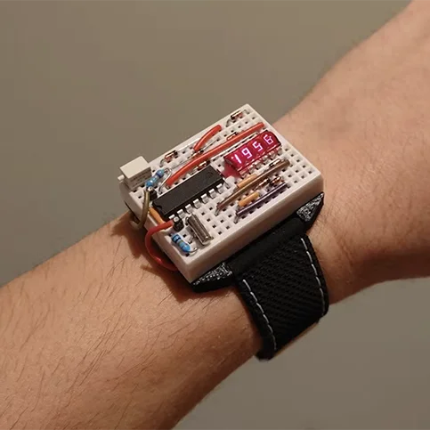
Copy Prompt@copilot I'd like to build geeky wristwatch with LED display. How would you approach building this? Please ask me questions to help me design this.
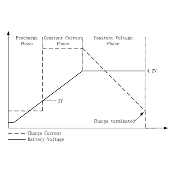
Copy Prompt@copilot here's a plot of the charging profile of U2. What charging phase would it be in at 3.2V?
Copy Prompt@copilot can you choose 4 digital pins on the ATMega328P-AU that I have here to use as GPIO given that I am already using some pins for reset, the external clock, UART, and I2C.
Copy Prompt@copilot what is the maximum frequency I can reach without an external crystal on U6?
Copy Prompt@copilot what resistor do I need to limit the current on LED1 while being driven by U1?
Copy Prompt@copilot can you help me debugging this circuit, and help me understand if there's any problems?
Copy Prompt@copilot can you check all my components in my schematic and tell me if I am missing any manufacturer part number fields?
Copy Prompt@copilot please review this block diagram and compare it to my project, is there anything I'm missing?
Copy Prompt@copilot what components do I need to power a 30w speaker to this audio driver amplifier?
Copy Prompt@copilot can you suggest a suitable ADC for microphone pickup going through an Arduino Uno?
Copy Prompt@copilot I want to build a PCB that uses a solar panel to charge a single cell LiPo battery. I want to measure ambient pressure with a microcontroller and send that over WiFi. What are all the components I would need?
Copy Prompt@copilot can you suggest an alternative to C1 that meets the same specs but is more cost-effective?
✨ Pro Tip: Use @tools to give Copilot more direction
Flux Copilot has a range of tools to help you through your design process. For the best results, use one tool at a time. This helps Copilot focus on a single task, making its responses more accurate and actionable.
- Use @library to direct Copilot to search Flux’s library of components. This is useful when you want to insert components that are in the parts library.
- Use @file when you want to direct Copilot to access datasheets, PDFs, or other documents that are attached to your project or components when conducting detailed analysis. You can also attach files to the prompt itself.
- Use @calculator when you want Copilot to calculate a value with deterministic instead of relying solely on AI reasoning.
- Use @code to create Python code snippets to create graphs, simulate, or validate design ideas.
- Use @help to get guidance on using Flux features and best practices.
Flux Copilot is here to make hardware design more straightforward and efficient. By following these prompts and tips, you can streamline your workflow, reduce errors, and tackle each step of your project with confidence. Feel free to share your results and favorite prompts in our Slack Community.
Happy designing!
Copy the Prompt and Try it Now
Design a low-noise microphone preamplifier for an electret condenser mic feeding a 24-bit ADC. You must calculate the bias network, gain-setting resistors, coupling capacitors, input high-pass cutoff, output anti-aliasing RC, and decoupling layout. Follow the op-amp and microphone capsule datasheets, ADC input requirements, and industry best practices. It will be integrated into a design. Supply: 3.3V analog rail. Mic bias: 2.0 V through resistor, current ~0.5 mA. Target gain: 20 dB to 40 dB switchable. Bandwidth: 20 Hz to 20 kHz. Input noise target: as low as practical. Include pop-suppression considerations and star-grounding strategy.
💡 Did you know that one of the capabilities of Flux Copilot, an AI powered hardware design assistant is its ability to calculate the total resistance between any two points in your schematic diagram? You can effortlessly determine the overall resistance, making complex calculations a breeze. Try Flux now, and best of all, it's completely free!
This means you don't need to do any calculations or formula anymore. Through a simple chat interface, just simply ask Copilot,
"@copilot what is the total resistance across terminal 1 and terminal 2?"
and wait a moment for Flux Copilot to response with the calculated total resistance value. It can even determine series or/and parallel resistor configuration automatically. It's like your holding a physical ohm meter and reading the actual resistance of a circuit. See it for yourself!
Understanding Parallel and Series Resistor Configurations
As electronics enthusiasts and professionals, we are always on the lookout for tools that can streamline our design process and improve our understanding of circuit behavior. The parallel and series resistor calculator is one such indispensable tool that enables efficient and accurate analysis of resistor networks. In this comprehensive guide, we will explore the concept of parallel and series resistors, the importance of resistor calculators, and the benefits they provide.
Parallel Resistors
Parallel resistors refer to resistors connected end-to-end, sharing the same voltage across their terminals. When resistors are connected in parallel, their combined resistance is less than the smallest individual resistor's value.
The total resistance in a parallel configuration is given by the formula:
1/R_total = 1/R1 + 1/R2 + ... + 1/Rn
Series Resistors
Series resistors are connected in a way that the end terminal of one resistor is connected to the starting terminal of the next resistor. In series configuration, the current flows sequentially through each resistor, and there is only one current path through the entire resistor network. The resistors should beconnected end-to-end, with no junction points or branches between them. Worth noting that same current flows through each resistor in this configuration, and the voltage drop across each resistor is proportional to its resistance.
The total resistance in a series configuration is simply the sum of the individual resistances:
R_total = R1 + R2 + ... + Rn
The Need for Parallel and Series Resistor Calculators
Manual calculations can be tedious, time-consuming, and error-prone, particularly when dealing with multiple resistors or complex circuits. This is where parallel and series resistor calculators come into play, offering valuable benefits such as:
- Simplified and accurate calculations
- Time and effort savings
- Enhanced circuit analysis
- Reduced risk of design errors
How Parallel and Series Resistor Calculators Work
Parallel and series resistor calculators are designed to provide quick and accurate results for resistor networks. These calculators generally include the following features:
- User-friendly interfaces for entering resistor values
- Options for selecting parallel or series configuration
- Auto-calculation of total resistance
- Conversion between different units (e.g., ohms, kilohms, or megaohms)
Applications of Parallel and Series Resistor Calculators
These resistor calculators are valuable tools for professionals and hobbyists alike. Some common applications include:
- Circuit design and analysis
- Troubleshooting existing circuits
- Component selection for specific resistance values
- Educational purposes (e.g., teaching and learning about resistor networks)
Parallel and series resistor calculators are essential tools for anyone working with electronic circuits. They simplify calculations, save time and effort, and reduce the risk of design errors. By understanding their significance and choosing the right calculator, you can ensure that your projects run smoothly and efficiently. So, go ahead and harness the power of these indispensable tools to elevate your circuit design skills to new heights.