November 10, 2023
Why Atmega328p is Still a Top Choice for Microcontroller Projects in 2023
Share
BuildWithFlux


A curated collection of PCB and hardware projects crafted by our talented Flux community.
Starting a new hardware project can be overwhelming, but the completely overhauled Copilot simplifies the process by guiding you through component selection, spec verification. Just describe your goals and Copilot engages in a focused conversation to refine your requirements like a seasoned hardware engineer.
Ask me a structured set of questions (about 5 one at a time) to help brainstorm and outline the most important parts of a project including the critical technical requirements, including power, components, performance, constraints, Use case etc
Always provide multiple options where applicable, considering trade-offs in cost, efficiency, size, and performance. By the end of this process, I want:
1. A block diagram illustrating the system architecture.
2. A complete list of all components, including passives and active components.
Instead of wading through datasheets and Google searches, use Copilot to select appropriate parts for implementation, recommending main and alternative components that meet design requirements. Tip: You can use tool like @library to direct Copilot to search the part library, or @file to direct Copilot to use datasheet details in it’s responses.
@library List out 5 switching regulators that I can use for my project with a maximum output current of 2A. Include key parameters such as input voltage range, output voltage range, switching frequency, efficiency, and package type.
@file extract the following details from the datasheet of @U2
1. Key features
2. Functional Pin Description
- List each pin with its name, function, and relevant electrical characteristics.
3. From the Typical Application Circuit:
- List all components present along with their values in a table format.
- Describe explicitly how each pin is connected.
4. Any circuit-Specific Design Notes
Identify alternative components for @U4 with similar functionality, pin configurations, and electrical characteristics. Include key differences and trade-offs.
@file extract the absolute maximum ratings of @U1 including voltage, current, and thermal limits. Present the data in a clear table format.
@file Explain @U1 in detail, including its purpose, key functions, and common applications. Describe how it operates within a circuit and any notable characteristics. Also, explain the family or series this component belongs to, highlighting its variations, key differences, and typical use cases compared to other models in the series.
@file Extract the recommended operating conditions for @IC2. Retrieve key parameters such as supply voltage range, operating temperature range, input/output voltage levels, and other relevant conditions specified for optimal performance.
Compare LMR33630ADDAR and MP2451DJ-LF-Z in terms of efficiency, output ripple, load regulation, and thermal performance. Highlight key differences in topology, switching frequency, and suitability for a [specific application, e.g., battery-powered wearable]. Provide a recommendation based on [input voltage range, output voltage, current requirements.
Analyze all the parts in the project context and generate a consolidated parts table that optimizes component selection. Specifically, apply the following consolidation rule:
- Identify passive components (resistors, capacitors, inductors) with the same values but different MPNs (Manufacturer Part Numbers).
- Propose a single standardized MPN for each unique value, prioritizing parts with better availability, and popular supplier.
Present the table clearly. The table must strictly list and analyze all passive components in the project context. It must not use vague terms such as “etc.” or truncate the list in any way. The table should have the following headers (Original Part Category (e.g., Resistor, Capacitor, Inductor), Original Values/Specs (e.g., 10kΩ, 1μF, 100mH), Original MPNs (List all variants found in the project), Proposed Consolidated MPN (Recommended single part), Reason for Consolidation (e.g., same specs, better tolerance, reduced part diversity)
Copilot isn’t just here to answer questions—it can take direct action in your project, helping you place components, modify properties, and refine your design faster than ever. Instead of manually searching for parts or tweaking values one by one, you can ask Copilot to handle specific tasks, like adding a resistor with a defined value or updating a component’s footprint.
When Copilot detects an action it can execute, you’ll see an action button appear—click it to apply the change instantly. If you don’t see a button, try rephrasing your request or breaking it into smaller steps. While Copilot can’t yet generate an entire schematic at once, it’s great at guiding you through the process, handling tedious tasks, and keeping your workflow smooth.
I want the 555 timer to operate at a frequency of 1.5 kHz.
@library add the following components to the project:
- NE555 Timer IC
- 2-Pin Terminal Block Connector (for power input)
- Resistors:
- R1 = 10kΩ
- R2 = 100Ω
- R3 (Current-limiting resistor for output)
- Capacitors:
- C1 = 100nF (0.1µF)
- C2 = 0.1µF (Decoupling capacitor)
- Diode: 1N4148
- LED
- Ground connection
@library add the following components to this project; NE555 Timer IC, 2-Pin Terminal Block Connector (for power input) and two 0603 1k ohm resistors
When working on a design, precise calculations are key—but instead of crunching numbers manually, Copilot can help streamline the process. Whether you need to size a resistor, calculate power consumption, or verify signal integrity, you can use Copilot to gather equations and relevant data before running calculations.
Start by pulling in the necessary formulas and values using @file or @library, ensuring you have all the details upfront. Once you’ve gathered the required inputs, use the @calculator tool to perform the calculations accurately. Taking this structured approach will help you get the most reliable results from Copilot.
@file obtain the equation for sizing the inductor for @U2, along with the required parameter values needed for the calculation.
@calculator calculate the inductor size for U2 needed for my project (Vin = 5V, Vout = 3.3V, Iout = 1A)
@calculator calculate the required PCB trace width for the 12V power rail according to the IPC-2221 standard. The trace should handle a current of 3A with a maximum allowable temperature rise of 10°C. Assume a copper thickness of 1oz and an ambient temperature of 25°C.
@calculator calculate the required decoupling capacitance for @C2 and @C3 considering ±50mv noise/ripple range.
Focuses on early project development to establish a solid project foundation.
@copilot, use mermaid-formatted block diagrams to generate 2 well-detailed architecture design of this project for comparison. Make sure to use the technical and functional requirements information.
@copilot, I’m designing a custom voice-controlled speaker and I initially want it to have buttons, Bluetooth, Wi-Fi, and rechargeable battery. Help me brainstorm and develop a comprehensive product requirements document. Ask me one question at a time, waiting for my response before moving to the next question.
@copilot, validate the the suggested architecture in the block diagram matches the product requirements set for this project. Point out any missing blocks that would be needed to satisfy the requirements.
Brainstorm and optimize modular circuit blocks for faster hardware development.
@copilot, based on my requirements, help me figure out the best power architecture for this project. What should the power tree look like?
Involves choosing appropriate parts for implementation, recommending main and alternative components that meet design requirements.
@copilot, here's the block diagram of this design. In a table format, recommend at least 3 IC for each block highlighting the electrical characteristics of the IC and why you recommended it.
@copilot, list all components specified in the datasheet of U1 for building the typical application circuit. Present the information in a detailed table format with equations needed to size the components.
@copilot, outline the electrical characteristics of U4 as detailed in the datasheet. Then, suggest at least four drop-in replacement parts, presented in a table format with the columns
@copilot, query all components in the schematic that do not have an assigned manufacturer part number (MPN). Compile these components into a table format with the following details: Designator, Component Function, Electrical Properties, and Recommended MPN (Provide a list of recommended part numbers based on the component's properties, focusing on the most popular and widely available parts).
Focuses on optimizing component selection and management, including consolidating similar passive components and addressing part obsolescence to streamline the bill of materials and reduce costs.
@copilot, perform a BoM consolidation review to identify passive components (resistors, capacitors, and inductors) that have similar but different values (within ±50%) and the same package code. The goal is to simplify the BoM and reduce costs by replacing these components with a single value where possible, without affecting the circuit's functionality.
For each group of similar components, compare their electrical and mechanical characteristics, then identify a single value that can replace the others. Provide a detailed comparison table for each group, listing the designators, component values, package codes, and the proposed consolidated value, along with key specifications and any additional notes. Document the final proposed consolidated BoM in a table format.
@copilot, identify all components in the schematic that are either obsolete or not recommended for new designs (NRND). Compile these components into a table with the following details: Designator, Description/Function, Obsolete/NRND Status, Recommended Alternative Parts (Suggest at least 2 alternative components and their MPN that are current, widely available, and suitable replacements, based on the original component's specifications).
Involves precise calculations for sizing various components often using Python for accuracy and presenting results in detailed tables.
@copilot, from the datasheet of U1 obtain equations used to
Calculate these values using python and present the results in a clear and detailed table.
@copilot, use Python to calculate the load capacitors for Y1 using the information from its datasheet.
@copilot, use the datasheets of LED D5 and D2 to obtain electrical characteristics needed to calculate the appropriate current-limiting resistor value. Then use python to calculate the value and present it in a well detailed table forma.
Involves detailed examination of integrated components to ensure proper component selection and usage in the design.
@copilot, from the datasheet of U2 List the pin names, functions, and additional attributes for the IC. Include the following details for each pin in a table format: Pin Name, Function, Pin Type (e.g., power, ground, signal), Pin Direction (e.g., input, output, bidirectional, passive), Default State (e.g., high, low, floating), Voltage Level (if applicable), Additional Notes (e.g., pull-up/pull-down resistor, special considerations).
@copilot What are the absolute maximum ratings for U5? Identify any critical components that must be carefully selected to stay within these limits and present the results in a well detailed table format.
Utilizes Python to create visual representations of design data to assist in analysis and decision-making.
@copilot, use python to plot a bar graph showing the most expensive components in this design.
Provides thorough checks of specific circuit elements to verify correct calculations and implementation in the schematic and layout.
@copilot, list all ICs and the decoupling capacitors attached to each. Ensure to include all ICs present in the design, including digital ICs, power converters, LDOs, etc. For every IC, clearly state:
@copilot, review the design to ensure all current-limiting resistors for LEDs are correctly calculated for a current range of 1mA to 10mA. Follow these steps:
@copilot, determine the efficiency of U4 at various load conditions, considering that the input is a battery with a voltage range from 4.2V (fully charged) to 3.3V (low battery level). Identify which components in the circuit affect this efficiency and present that in a detailed table. Finally, use python to plot a graph showing the efficiency of U1 across the range of load conditions and input voltages.
Generates test plans and collaborative workflows, ensuring your hardware is manufactured error-free.
@copilot, create a detailed step-by-step plan table for this project to verify its functionality.
@copilot, develop an FMEA (Failure Mode and Effects Analysis) report in a table format that analyzes the systems schematic, each unique component specification, and operational parameters. It should identify critical failure modes, assess their impact, and recommend mitigation actions based on severity, occurrence probability, and detectability. Include columns such as: process step, potential failure mode, potential failure effect, S, O, D, RPN, Action Recommended, and any other you see fit.
Copilot can help get you started quickly by understanding the requirements and providing guidance.
@copilot here's a block diagram I've been working on. Can you suggest ICs I might use to implement this in Flux?
@copilot I'd like to build a smart curtain that opens or closes based on the amount of sunshine I want to enter my room. How would you approach designing this? Please ask me questions to help with the development.
@copilot I'm designing a PCB for a medical device that measures heart rate and temperature. Can you give me the list of components I will need?
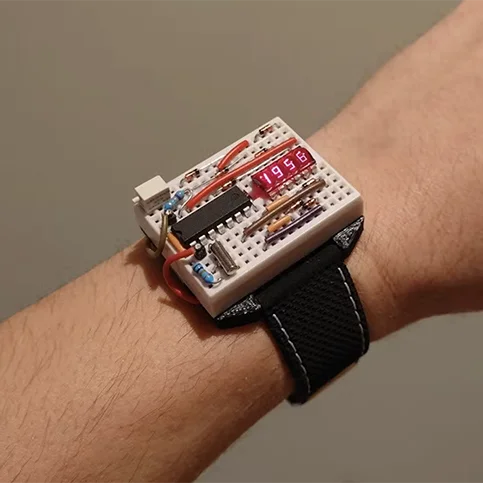
@copilot I'd like to build geeky wristwatch with LED display. How would you approach building this? Please ask me questions to help me design this.
Copilot can connect complex parts for you, explore design options, and provide a bill of materials for a target project.
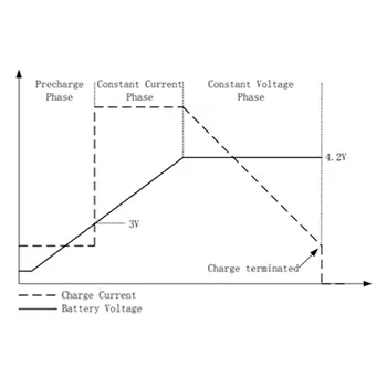
@copilot here's a plot of the charging profile of U2. What charging phase would it be in at 3.2V?
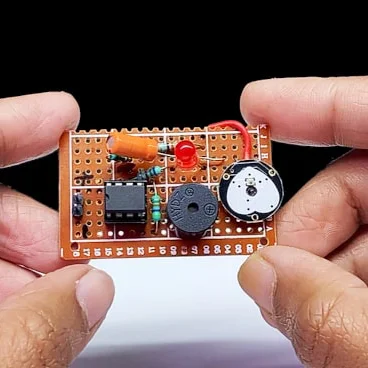
@copilot, how would I connect these parts to make the LED flash at 1kHz?
@copilot, how would I connect these two HDMI connectors as a pass through?
@copilot, how should I connect RP2040 and TFT LCD?
@copilot can you choose 4 digital pins on the ATMega328P-AU that I have here to use as GPIO given that I am already using some pins for reset, the external clock, UART, and I2C.
Copilot can understand datasheets and reference them in its responses. This means you get more accurate responses when asking Copilot questions about specific parts.
@copilot what's the max voltage I can supply to U2?
@copilot can U2 withstand intense operating temperatures even without a heatsink?
@copilot what is the maximum frequency I can reach without an external crystal on U6?
@copilot I'm a firmware engineer. How do I configure an interrupt on a pin for U4?
@copilot what are the clock requirements for U4?
Copilot answers questions about how to use Flux by referencing our documentation. So, instead of getting stuck and searching documentation, you can stay in the flow and get the help you need without leaving your project!
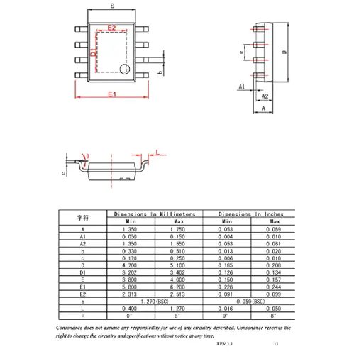
@copilot can you explain the different dimensions of this footprint diagram?
@copilot how do I know if a part has a simulation model?
@copilot how do I connect ground to these components?
@copilot I can't find part on the library what do I do?
@copilot how do I know my projects are safe and private?
@copilot what resistor do I need to limit the current on LED1 while being driven by U1?
@copilot can you help me debugging this circuit, and help me understand if there's any problems?
@copilot can you check all my components in my schematic and tell me if I am missing any manufacturer part number fields?
@copilot how would I decrease the distance between my ground fill and my vias?
Copilot can provide valuable recommendations to optimize your design based on constraints and specifications.
@copilot please review this block diagram and compare it to my project, is there anything I'm missing?
@copilot what components do I need to power a 30w speaker to this audio driver amplifier?
@copilot can you suggest a suitable ADC for microphone pickup going through an Arduino Uno?
@copilot can I use U1 to make a 20db gain op-amp?
@copilot I want to build a PCB that uses a solar panel to charge a single cell LiPo battery. I want to measure ambient pressure with a microcontroller and send that over WiFi. What are all the components I would need?
Copilot can offer tailored suggestions and analyze tradeoffs based on your project goals, constraints, and specifications.
@copilot can you suggest an alternative to C1 that meets the same specs but is more cost-effective?
@copilot are there any alternatives to U2 that have better availability?
Flux Copilot has a range of tools to help you through your design process. For the best results, use one tool at a time. This helps Copilot focus on a single task, making its responses more accurate and actionable.
Flux Copilot is here to make hardware design more straightforward and efficient. By following these prompts and tips, you can streamline your workflow, reduce errors, and tackle each step of your project with confidence. Feel free to share your results and favorite prompts in our Slack Community.
Happy designing!
At the core of many electronic projects lies the ATmega328p, an 8-bit microcontroller belonging to Atmel's AVR series running off of a Reduced Instruction Set Computer (RISC) architecture. RISC architecture is advantageous due to its simplicity, which results in faster execution, improved compiler optimization, and better support for parallelism.
The ATmega328p is equipped with 32KB of ISP (In-System Programmable) flash memory, 1KB of EEPROM (Electrically Erasable Programmable Read-Only Memory), and 2KB of SRAM (Static Random-Access Memory).
Embedded systems often require the ability to store data persistently. The ATmega328p addresses this need with its onboard EEPROM. This non-volatile storage space is crucial for storing data that needs to persist across power cycles.
Developers can utilize the EEPROM for storing configuration parameters, calibration data, or any other critical information that requires retention.
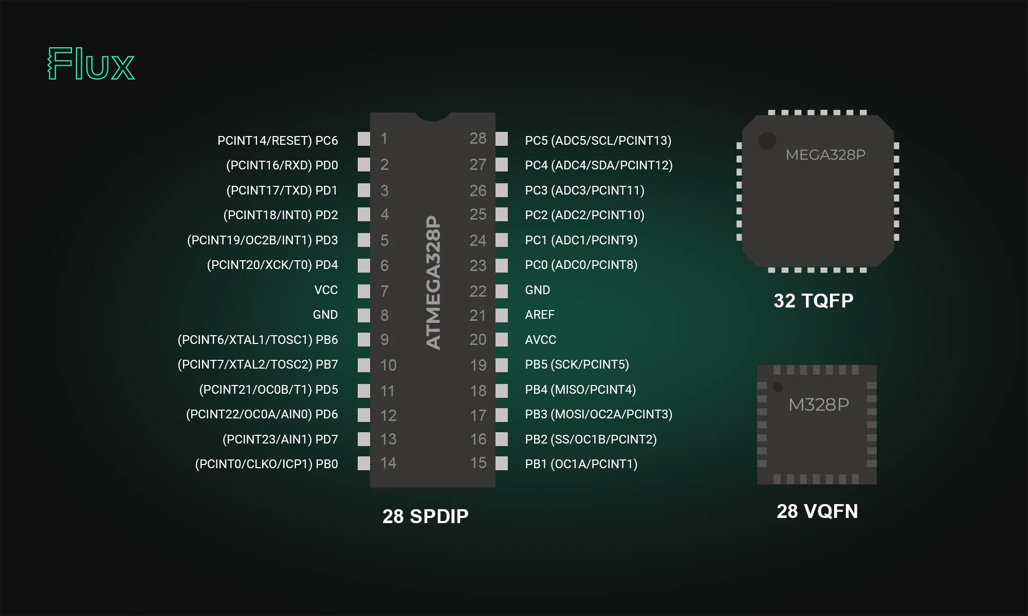
With 32 pins, the large number of digital and analog I/O pins is a key strength of the Atemga328p. The device boasts 23 general-purpose I/O (GPIO) lines, including analog inputs for sensor integrations. With a total of 6 analog input pins, developers can seamlessly interface with various sensors, converting real-world analog signals into digital data for processing.
There are two VCC pins (pin 4 and pin 6) and one AVCC pin (pin 18) for voltage supply, three GND pins (pin 3, pin 5, and pin 21) for grounding, and additional pins for 22pF capacitors, vital for stabilizing the 16MHz crystal oscillator.
The ATmega328p excels in managing inputs and outputs with three bi-directional GPIO ports, two 8-bit ports—PortB and PortD–and one 7-bit port–PortC. These ports serve as I/O interfaces, allowing users to control or read from external devices. Each I/O port pin may be configured as an output with symmetrical drive characteristics, or an input with or without pull-up resistors of 20 - 40 K ohms. Each bit in a Port corresponds to a specific pin, granting granular control over the connected peripherals. Understanding the DDR (Data Direction Register) is crucial for manipulating the ports. It determines whether each pin in a port operates as an input or output. For instance, setting a specific bit in DDRB to 1 configures the corresponding pin in PortB as an output.
Ensuring a stable 5V supply is vital for consistent performance, and the ATmega328p comes equipped with robust voltage regulation capabilities. The microcontroller operating voltage range is 1.8V to 5.5V, making it adaptable to various power supply configurations.
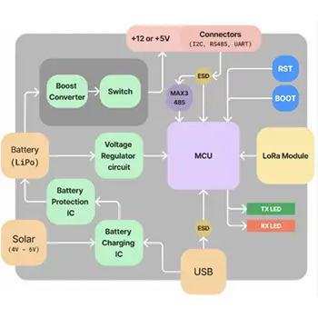
The ATmega328p offers several power-saving modes, allowing developers to tailor power consumption based on project requirements. These modes are particularly beneficial for energy-sensitive applications, extending battery life, or enabling solar-powered solutions.
Notable features of the ATmega328p include a plethora of options for serial communication (SPI, I2C, USART), two 8-bit Timer/Counters, one 16-bit Timer/Counter, and a 6-channel 10-bit A/D converter (ADC) enabling analog signal acquisition.
The atmega328p supports SPI, I2C, and USART, essential for communicating with other microcontrollers or modules.
A dedicated SPI interface enables high-speed, full-duplex communication. The following table outlines the key pins associated with SPI:
Integrating SPI-enabled devices, such as external flash memory or display modules, becomes seamless with the ATmega328p.
I2C support further extends the microcontroller's communication capabilities. The ATmega328p's I2C pins are:
This protocol is invaluable in projects requiring communication with multiple devices on the same bus.
USART enables serial communication and is crucial for interfacing with devices like GPS modules or Bluetooth modules. The USART pins on the ATmega328p are:
The ATmega328p provides flexibility in choosing between internal and external clock sources. This choice, such as opting for an external 16MHz crystal, significantly influences precision and power consumption.
Built-in timer counters enable the ATmega328p's time-sensitive capabilities. These timers provide accurate timing intervals and pulse-width modulation (PWM) functionality.
The ATmega328p’s 6-channel 10-bit Analog-to-Digital Converter (ADC) significantly enhances its capability to acquire and process analog signals. This ADC functionality is instrumental in translating real-world analog data, such as sensor inputs, into digital values that can be processed by the microcontroller.
This module is capable of translating analog voltages into a 10-bit number ranging from 0 to 1023, based on the inputted range of expected voltages (from 0 V to the voltage of the VCC). The microcontroller provides flexibility in choosing from six input sources, but only one channel can be converted at a time. The ADC module operates with a conversion speed of approximately 15,000 samples per second (15 ksps), ensuring swift and efficient signal processing.
The ATmega328 and ATmega328P are microcontrollers from the same family but have some differences:
The ATmega328P is not discontinued. While there was an indication on a distributor's website (Mouser) suggesting that the ATmega328P-MU variant is scheduled for obsolescence and will be discontinued by the manufacturer, this information should be interpreted with caution.
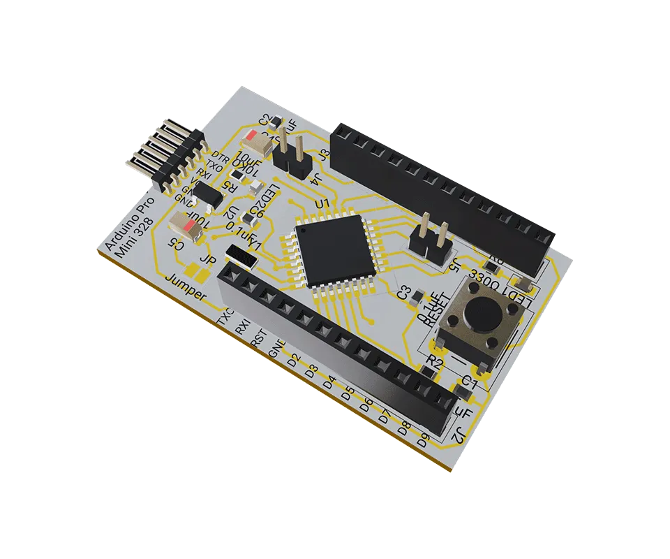
The Arduino Uno board, one of the most popular Arduino boards, uses the ATmega328p as its central processing unit. This integration has played a significant role in popularizing the ATmega328p, making it synonymous with user-friendly yet powerful microcontroller projects.
While Arduino offers easy access to the ATmega328’s capabilities, there are some applications that require utilizing the ATmega328p standalone, without the Arduino framework. Programming the ATmega328p standalone has a steeper learning curve, but provides a more granular and customized approach.


Understanding amps and volts is key to working with electronics. This guide explains their roles, relationship, and practical applications.
This holiday season is a great time to try something new and unleash your creativity with open-source hardware projects.

The blog post dives into the technical aspects of Multilayer Ceramic Capacitors (MLCCs), highlighting their importance in electronic circuits. It explains the construction of MLCCs, where layers of ceramic material and metal electrodes create a multilayered structure to store electrical energy.

In this article, we will discuss the key components of the Arduino Uno schematic, including the microcontroller, voltage regulator, USB interface, and passive components, and how they work together to make the board work.

In this article, we will explore Arduino Uno's fundamental concepts, specifications, and its comprehensive pinout details including programming with the Arduino IDE.

If you're looking to improve your understanding of schematic diagrams, this article is the perfect starting point. Let's explore the crucial role of circuits and components schematics in translating conceptual electrical designs into physical printed circuit board assemblies (PCBAs).
CO2 sensors monitor air quality, helping prevent cognitive decline from high CO2 levels. They use various technologies for accuracy in different settings. These sensors are vital for health, efficiency, and safety.

A comprehensive guide to using solder flux in electronics soldering. Soldering flux is used to clean and prepare the surfaces of the components that need to be joined. It helps to remove oxidation and other contaminants that can prevent a strong bond from forming. Flux also reduces surface tension, allowing the solder to flow more easily and improves the wetting of the components.

In this post, we’ll explore five common mistakes companies make when contracting PCB design and how you can avoid them by using tools like Flux to keep your project on track, from concept to completion.
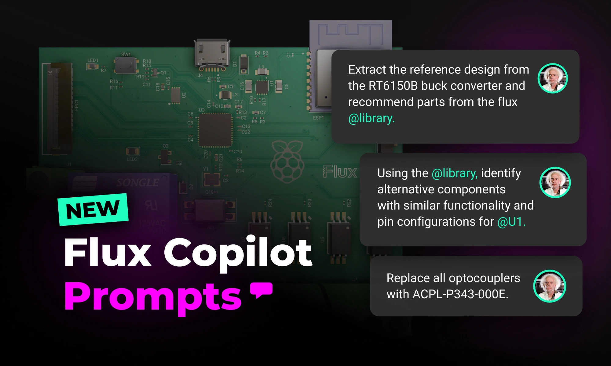
With the latest release of Copilot it isn’t just smarter—it’s hands-on, placing components and applying bulk changes to your project instantly. But to get the most out of it, knowing how to craft the right prompt is key.

If you're a lover of smart home devices, you're likely buzzing with excitement over Arduino's recent collaboration with Silicon Labs. We are too, and we’re even more excited to bring the power of this collaboration to life on Flux. As of today, we’re excited to announce that engineers can fully design Arduino-based Matter boards with Flux.
Streamline PCB development with NextPCB templates in Flux, featuring pre-set constraints, AI-assisted layouts, and seamless manufacturing transitions.