Today, we’re excited to share our Summer Update to Flux AI Auto‑Layout, a collection of improvements designed to make one‑click PCB routing more reliable, transparent, and adaptable to your real‑world workflows.
We’re launching our Stackup Editor: a new and improved way to select your PCB stackup that requires less time, less effort, and is less prone to errors. This is another massive step towards creating a single place where designers can collaborate with each other and the industry as a whole.
Selecting your PCB’s stackup has always been painstaking and unintuitive. First, you have to talk to the fabrication house, who will send you their stackup capabilities and tolerances via email and PDF. Then, it’s your job to take that information and transpose it back into your design tool, double and triple-checking that you didn’t make any errors in the process. So much back and forth inevitably leads to disorganization, information loss, and sometimes even failure. Not to mention lost time in the process.
If fabrication houses have standardized stackups, why are there so many hoops to jump through just to implement them into your design?
With Flux’s Stackup Editor, we change the narrative. With a simple and intuitive interface built into the tool, the Stackup Editor gives engineers an improved stackup workflow. Just go to your PCB layout, select “Stackup” under “Object-specific rules”, and find everything you need in one centralized location.
Not only can you edit and create stackups with minimal effort, but you can now also leverage Flux’s community of over 175,000 electrical engineers to take the hard work out of the process. With thousands of projects available to you from the community, you never have to start from scratch. Instead, you can simply find a project that is similar to yours and use that stackup as a template for your own design.
Finally: stackups no longer live in your email inbox, they live in the tool. And with that, you can save yourself from the wasted time, money, and effort that has been industry-standard for far too long.
More importantly, the addition of Stackup Editor aligns with our ultimate goal of creating a single, centralized platform for all of the hardware industry to collaborate.
With the Stackup Editor, fabrication houses themselves can directly input their stackup options into Flux as templates for designers to choose from. Just go to the fabrication house’s Organization page, find a stackup template from them that matches your project, and fork it for your own design.
At launch, you can choose from dozens of Stackup templates, including:
With that kind of first-party input from the houses themselves, you can feel confident that your stackups are ready for production before you even get there.
The Stackup Editor is another massive step towards creating a single place where designers can collaborate with each other and the industry as a whole. Now Flux offers one place where you can directly access parts from suppliers, designs and references from manufacturers, and stackups from fabrication houses.
If you want to get hands-on with the Stackup Editor, check out some of our templates and get started today!
For months, we’ve been adding new features and functions to Copilot to help make it the most powerful AI for hardware design in the world. Today, we’re announcing what might be the biggest upgrade yet: Copilot Vision.
Now, not only can you chat with Copilot, but you can also show it what you're working on. What does that mean? Copilot is now the first multi-modal AI for hardware design, and with that, a whole new world of possibilities has opened up for Flux users.
Hardware design can be tricky because so much of the thinking is visual and requires context. As an engineer, you’re expected to rely on visual resources like block diagrams, charts, and drawings. But these resources are usually confusing to interpret and separate from your actual design, making them lose their value quickly.
With Copilot Vision, you can now provide Copilot with images as a more natural way to communicate ideas and integrate those resources into your design. Imagine snapping a photo of a block diagram and Copilot instantly understanding what you're trying to build.
Simply provide Copilot an image as a file upload and ask your questions. Suddenly, visual resources are relevant and even powerful for sanity checks. Now, you can ask questions, learn, and get design reviews in entirely new and more effective ways.
Imagine you’re working on a project that’s based on an existing block diagram. You need to turn that block diagram into a working circuit, selecting the right components and connecting them in the right way. Normally this would mean reading through datasheets and application notes, but that gets confusing, time-consuming, and hard to keep track of.
Now that Copilot has vision, you have access to powerful new use cases that improve your hardware design workflow.
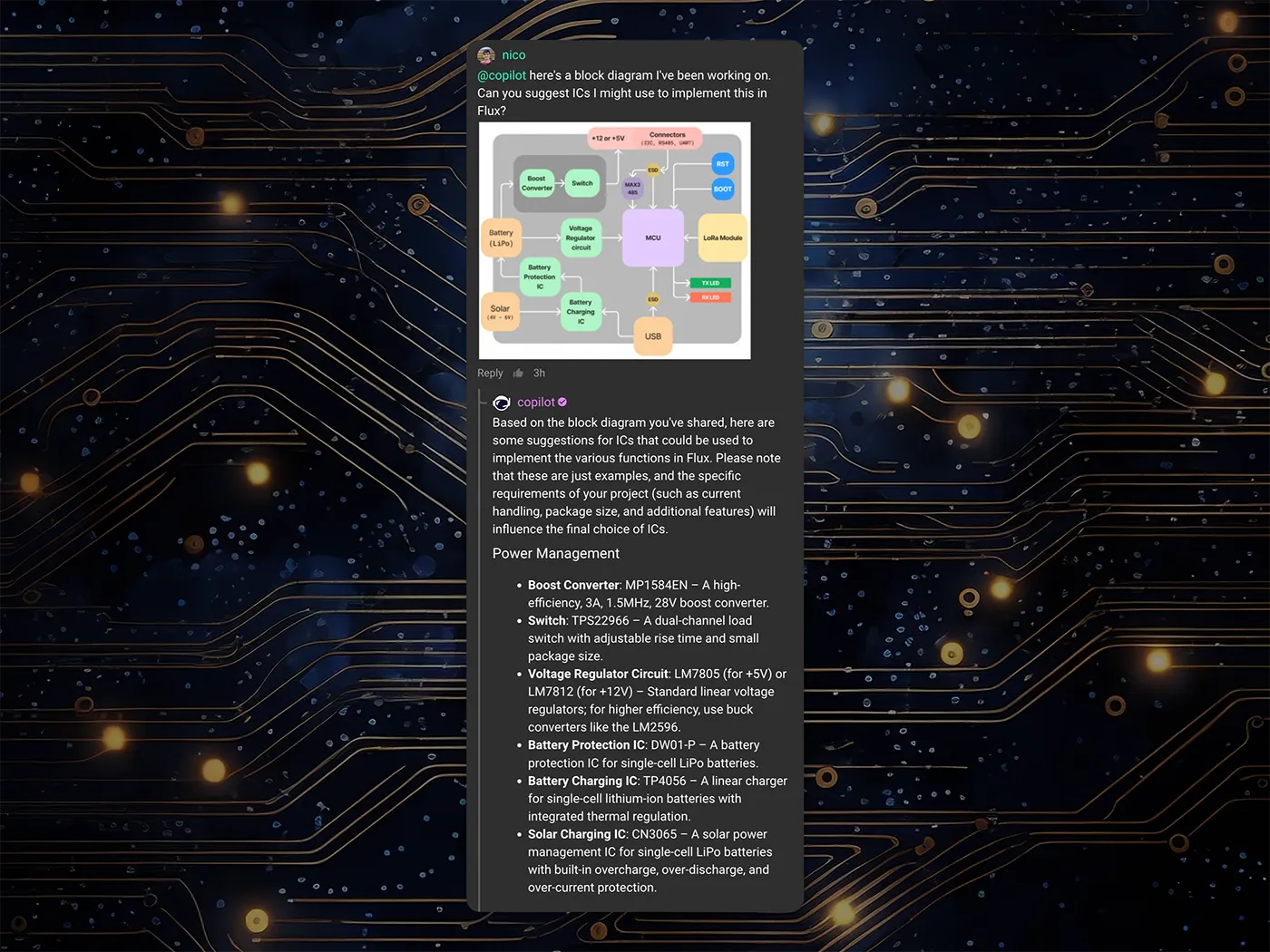
Part Recommendations: Trying to find the right parts to implement your design? You can now input a block diagram to Copilot and watch it recommend suitable parts for your design by intelligently parsing the diagram into functional sections.
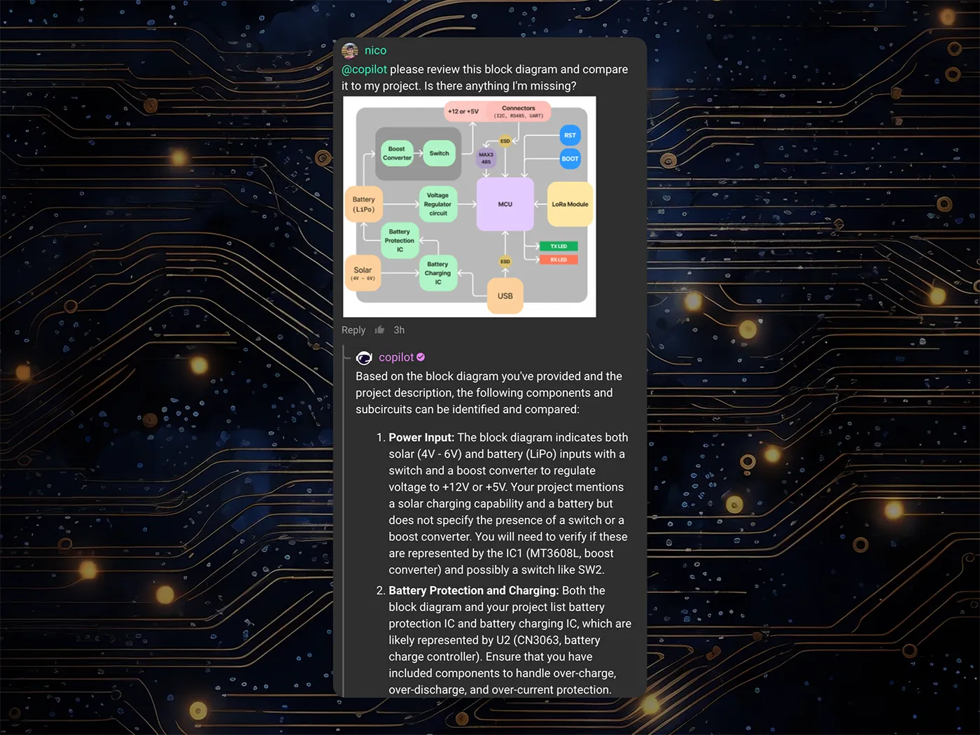
Design Review: Once you make your design, you’ll want to make sure you didn’t miss anything. Copilot can help ensure design quality by comparing your schematic diagram against a block diagram. Copilot's analysis catches discrepancies, such as missing elements in your design that appear in the diagram, and offers you suggestions for improvement.
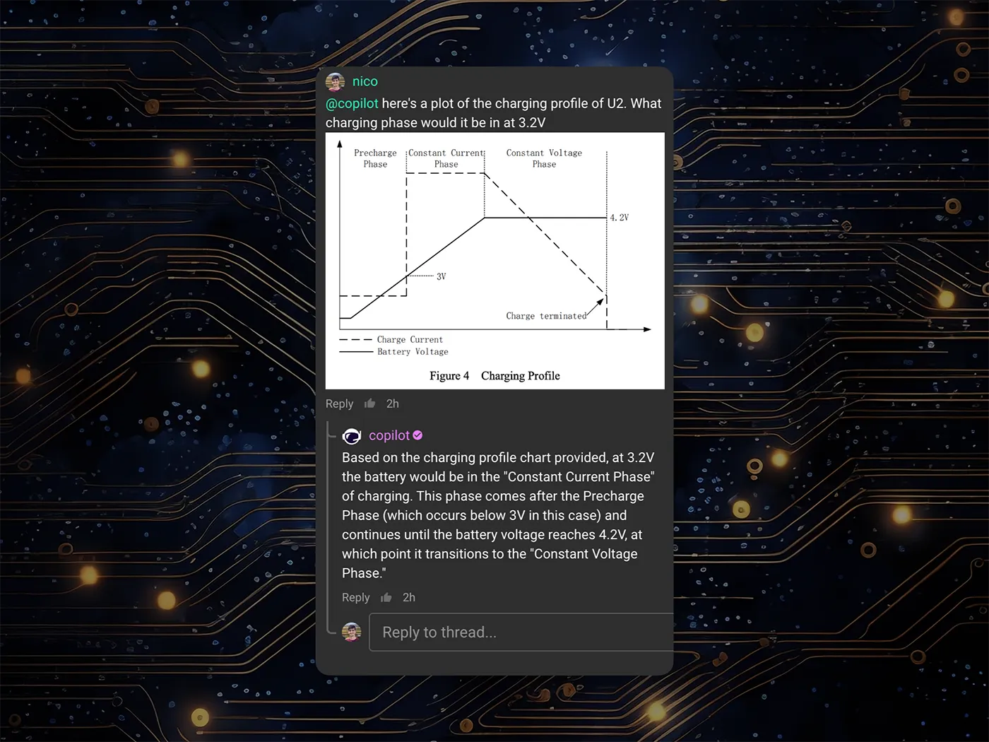
Chart Interpretation: Confused about how to interpret a chart on a datasheet? Just provide Copilot with an image of the chart and ask it in-depth questions. It will interpret your input and explain any aspect of the chart and how it relates to your hardware design needs.
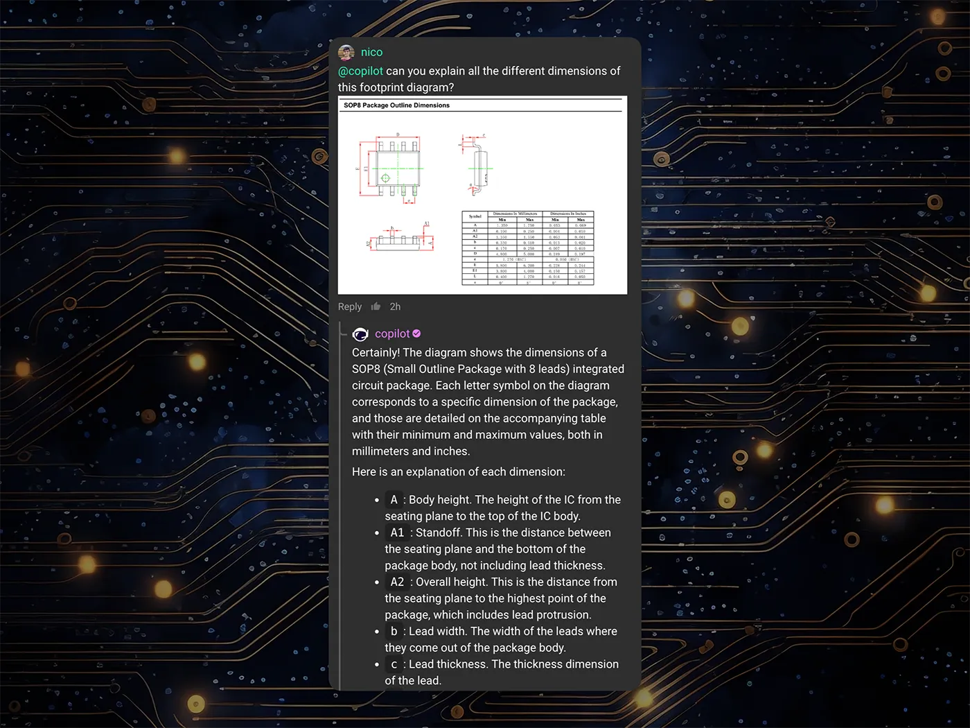
Dimensional Analysis for Footprints: Have you ever looked at the part drawings and been overwhelmed by all the information and dimensions? Now you can provide an image to Copilot and ask it any question about part dimensions. Copilot efficiently interprets and correlates them to real component footprints, even making educated guesses about component types based on project context.
This is a major step forward for Copilot, but we’re just scratching the surface of what’s possible. We believe that vision unlocks the doors to so much more down the road, but we’ll need your help! By trying out Copilot with vision, you can help us identify new use cases and steer the direction of Copilot’s future.
Try out Copilot today, and share your feedback with us through our Slack community. Tell us what works well, what could be better, and what other modes of interaction would you want to see us build into Copilot.
Today, we're thrilled to unveil Copilot Experts – a new suite of specialized AI models, each fine-tuned for specific tasks to deliver sharper accuracy and faster performance. Now, you have the power to easily select the AI model that best suits your current task, ensuring more precise and swift responses.
Today, we're thrilled to unveil Copilot Experts – a new suite of specialized AI models, each fine-tuned for specific tasks to deliver sharper accuracy and faster performance. Now, you have the power to easily select the AI model that best suits your current task, ensuring more precise and swift responses.
Accessing Copilot Experts is a breeze. Simply click on the Copilot icon in the comments or chat window, and select your desired expert from the dropdown menu. At launch, we are excited to introduce three distinct expert models:
Meet the original Copilot model, now known as the Generalist. This model is your versatile, jack-of-all-trades assistant, ready to tackle a wide array of queries with the same efficiency you've come to appreciate.
For instance, ask the Generalist:
@copilot can you explain to me what’s happening in this circuit?
The Librarian shines when it comes to parts inquiries and effortlessly navigating through datasheets. If you're looking to delve into specifics about a component, the Librarian is your go-to expert.
@copilot am I using the right amount of decoupling for U1?
This is your go-to for Flux product guidance. Have questions about how to use the tool? Don’t feel like sifting through the documentation? Just ask the Help Expert for the answers. For example:
@copilot how do I change the stackup of my PCB?
We recently launched Copilot Shortcuts, which are powerful pre-made questions that you can ask Copilot with the click of a button. With Experts, those Shortcuts now automatically route to the best Expert for the job - meaning you get the best answers without having to do any work.
Copilot Experts is a testament to all of the feedback we’ve gotten from the community over the last year. Try out the Copilot Experts today to see how we’re taking your feedback, and using it to make the best AI tool in the industry!
Today, we’re excited to be launching the next step in Copilot’s evolution: the Copilot Context Menu. It lets you access Copilot with the click of a button. Simply right-click on a component or project, and choose the prompt you want to use.
The Copilot Context Menu makes harnessing the power of Copilot easier than ever before. By giving users a list of predetermined prompts and actions to choose from, the Context Menu lets you access Copilot with the click of a button. Simply right-click on a component or project, and choose the prompt you want to use.

Some options include:
Copilot relies on Large Language Model (LLM) technology, whose quality and accuracy may vary. For this reason, it’s important to think of Copilot as a tool to augment your work, not a replacement for a real engineer. But, now that Copilot is even easier to use, the opportunities are endless.
As a professional, you can catch errors earlier on, save time, and reduce risks in your design. As a student, you can learn faster and get a deeper understanding of your designs. As anyone who loves hardware, you can have more confidence in your design knowing that a powerful AI has your back every step along the way.
Copilot keeps getting better, but it would be meaningless without the Flux community. The real power of Copilot lies in what each Flux user will create with it. We can’t wait to see what amazing designs you all come up with. So what are you waiting for? Try out Copilot today!
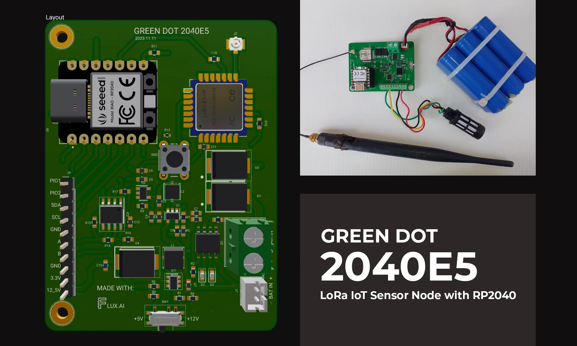
The blog details the creation of a LoRa IoT sensor node for agriculture, focusing on PCB design, power management, wireless connectivity, and sensor integration using the RP2040 microcontroller. It aims to bridge the technology gap in farming, enhancing productivity through data-driven insights.
I live nestled in the heart of an agrarian country. Here, the soil holds tasteful tales of the past and the future of our economy. If you like numbers, here’s a bunch for you, Agriculture contributes approximately 33% of our GDP and employs more than 40% of our total population. You see, my journey into this project wasn’t fueled by a quest for innovation, but if I end up innovating something, I accept that. It was fueled by a need to improve, even just a tiny bit, the current state of affairs. USAID published an article saying that in recent years agricultural productivity has stagnated. Current methods of farming are pretty archaic and if we are to depend on these same methods to boost our productivity, we risk being obsolete as well.
One of the biggest challenges that farmers currently face is the gap that exists between them and the technology that could improve their output. This project aims to eliminate that gap. I have built an IoT sensor node that can be deployed to the farm and collect important parameters for a farmer which can be analyzed and used to maximize productivity. With this aim in mind, I have to solve several challenges including:
To solve these four main problems, I started by drafting a block diagram that provides an overview of the electronics.

Generally, the aim is to have a node that includes a high-performance, low-power, low-cost microcontroller at the heart of the board which can support industry-grade sensors using RS485 protocols, a low-power wide area networking module, a power management circuit that can supply power to both the MCU and any peripherals connected.
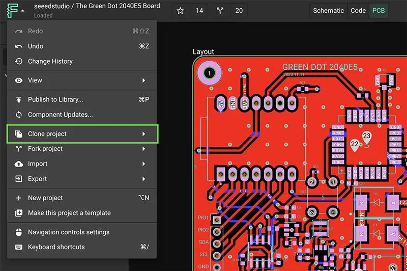
In this project, I will be describing how I accomplished that in the Green Dot Board. You can head to the Project and clone or fork it to have edit access.
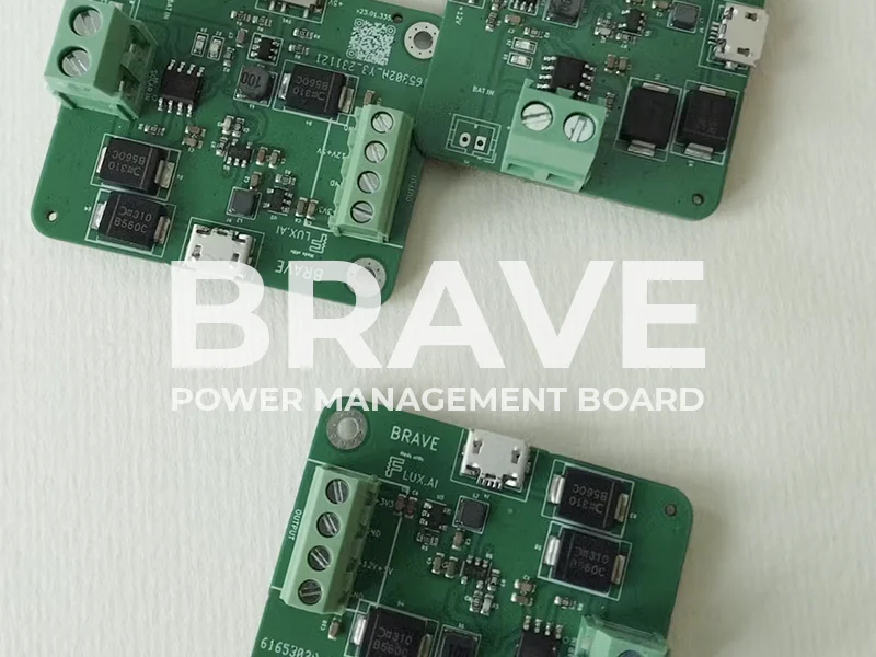
One of the most important features of the Green Dot Board is power management. As described in the core requirements of the system, is the ability to work autonomously for years without any power concerns. I therefore decided to start by designing a power management circuit and making sure that works fine first to de-risk the whole system.
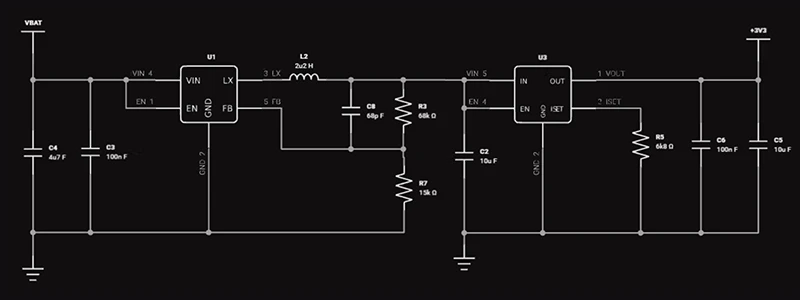
Most of the sensors that can be hooked onto this system require either 3.3V, 5V, or 12V. I therefore designed the power management circuit to be able to deliver all these powers. You can check out the Brave Power management circuit here. This board can be powered by either LiPo batteries, 4V - 6V solar power panels, or a Micro USB. From these inputs, there is a set of dedicated components to generate and regulate each of the mentioned outputs.
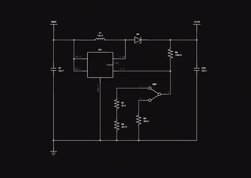
a) 12V and 5V Rail
Starting with the 12V and 5V rail, I used the high-efficiency MT3608L 1.2MHz step-up converter. I used a voltage divider circuit to adjust the output of the component and used an SPDT switch to enable switching between the 12V and 5V output.
Vout = Vref x (1 + R1/R2) where Vref = 0.6V as per the datasheet
b) 3.3V Rail
For the 3.3V rail, I first use an RT8059 converter which is a high-efficiency Pulse Width Modulated (PWM) step-down DC/DC converter, capable of delivering 1A output current over a wide input voltage range from 2.8V to 5.5V. This was very ideal for my case since the LiPo batteries I will be using have a nominal voltage of 3.7V, a maximum of 4.2V when fully charged, and a minimum of about 3.0V when fully discharged.

where the ripple current can be approximated as 30% - 40% of the maximum output current
I then used an ultra-low loss power distribution switch with a programmable current limit to protect the power source from overcurrent and short circuit conditions. Current limiting is set by connecting a resistor Rset from ISET Pin to GND. To get the value of the Rset you want, you can use the following equation.
Rset = 6800/Current(A)
c) Charging circuit
For charging the batteries, I used the CN3063 which is a constant-current /constant-voltage linear charger for single-cell Li-ion and Li-Polymer rechargeable batteries. This device is ideally suited for solar-powered applications but it can also work with the USB specifications. It has a regulation voltage preset at 4.2V with 1% accuracy but can also be changed using a resistor. the device accepts input voltages of 4.4V to 6V meaning we would have to use a small solar panel delivering about 5W.
Some interesting features I haven’t mentioned yet of this device include the following.
The charge current is set by connecting a resistor Riset from the ISET pin to GND. The ISET pin’s voltage is regulated to 2V during constant charge current mode.
Ich = (Vset / Rset) x 900
I then used two diodes to direct current from both USB and Solar to the charging circuit.

Improvements for a V2 level, so reading the value with an MCU will prove invaluable.
For wireless connectivity, LoRaWAN was an obvious selection. I won’t go deep into the theory behind LoRaWAN, all I can say now is that LoRaWAN stands as a low-power, wide-area networking protocol, leveraging the LoRa radio modulation technique as its foundation. Its primary function lies in establishing wireless connectivity for devices to the internet. For example, enabling your motion sensor to have a heart-to-heart with your alarm system and notify you when unprecedented motion is recorded.
LoRaWAN boasts several features that position it as an ideal fit for our IoT applications:
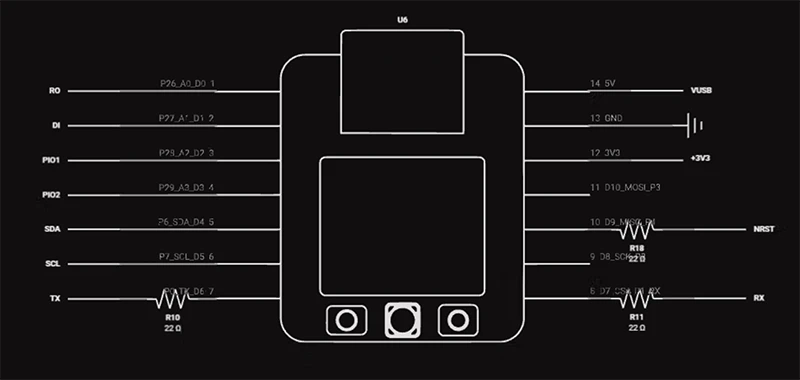
I decided to choose the SEEED Studio’s LoRa-E5 module because it has built-in AT command firmware, making it easy to create prototypes or applications with just a few simple commands. However, soldering the module onto the board was probably the most challenging bit of the whole Green Dot development process. The module is small, and I don’t believe I had the right tools to handle that kind of hand soldering. It was only after I got soldering flux, and a better soldering iron tip that I was able to finish the job.
Designing around this module is quite simple. I connect UART and NRST to the host MCU to send AT commands. In addition, I connect Pin24 to a tactile push button because the grounding of the module will force the module to enter Boot upgrade mode. This module works on 3.3V so I also make sure to provide that.
a) Registering our LoRa Module
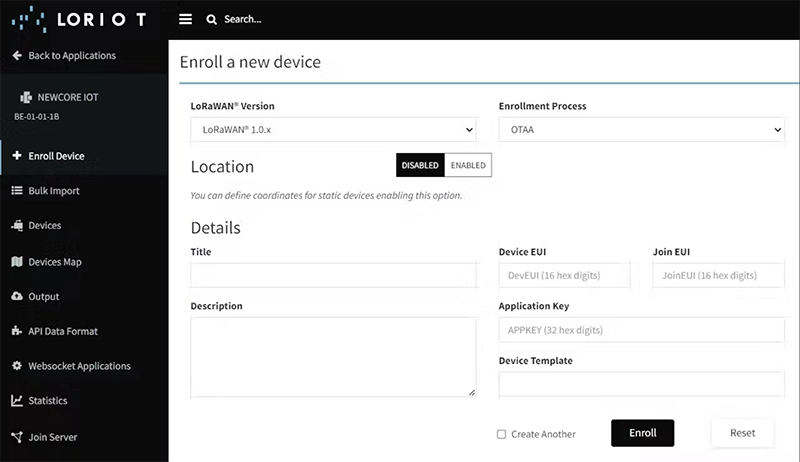
To register a device to a LoRaWAN platform, you can choose either of two options, Activation By Personalization (ABP) or Over The Air Activation (OTAA). One of the main differences between the two is that ABP offers simplicity and speed, while OTAA provides enhanced security through dynamic key exchange so for our case we will use OTAA to register our device.
When registering a device using OTAA (Over-The-Air Activation) in a LoRaWAN network, you typically need the following information:
I’ll be using Loriot for this demonstration because that was readily available to me, but the same concepts apply to other similar platforms like The Things Network (TTN). Step 1 would be to enroll a device by providing the generated keys and a name for the device.
The next step would be to make sure those same keys are written to the LoRa module. This can be done as shown below.
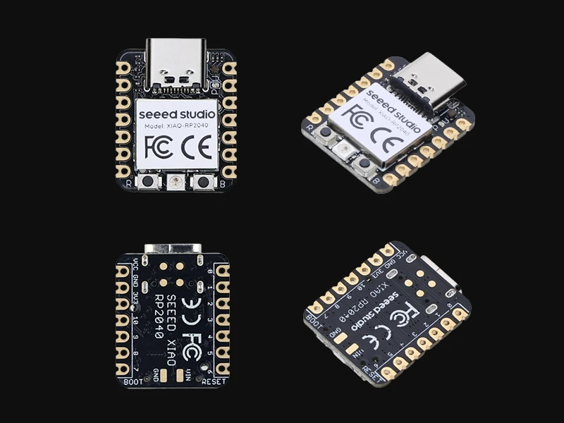
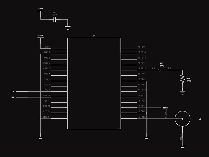
Choosing the right microcontroller is pivotal for the success of an IoT sensor node. Considering the requirements of low cost, low power, efficiency, and an easy development environment. I decided to go with the Seeed Studio’s XIAO RP2040. This breakout features the RP2040 microcontroller from Raspberry Pi bringing with it high performance, low cost, and ease of use to the microcontroller space.
Some of the features outlined on Seeed Studio’s website include:
This SEEED module has an onboard RGB LED which we will use to visually illustrate the state of the system.
Sensor Interface
When it comes to interacting with sensors, the green dot board can hook up UART, I2C, and RS485 sensors. The connection block also has a set of two pins which can be used as programmable IO pins using the RP2040.
For the RS485, I’m using the SP3485 a +3.3V low-power half-duplex RS485 transceiver with a 10Mbps data rate. The RS485 standard allows for multi-drop (multiple devices on the same bus) and long cabling lengths. In addition, it offers great noise immunity. Some of the sensors that can be connected include the following;

The supporting components around the RS3485 include a bypass capacitor, a pull-up resistor on the RO line, and a termination 120-ohm resistor at the end of the twisted pair A B cables. I used a 120 ohm because the twisted pair cable used in RS485 is defined to have a characteristic impedance of 120 ohms and so by adding a 120-ohm resistor at the end of an RS485 transmission line, the signal will be dampened by the resistor instead of reflected into the bus.
The last bit is to route to my microcontroller.
NOTE: During testing, I realized something that you might have already noticed from this schematic, I had forgotten to connect the ENABLE pins from the SP3485 to my microcontroller. This will be done in my second revision.
I wrote a simple MicroPython code to that sends some data to the cloud as proof of concept. The code can be found on my GitHub Profile. I started by writing simple functions to interact with the LoRa module and then used those functions to join the network and send data to the cloud.
In the main file, I start by importing the required libraries and defining the firmware parameters.
I then enter an infinite loop that first checks whether It’s the first time we are running the code, if it is then we join the network, if not we continue with the rest of the code that first reads sensor values and then sends then converts the values into hexadecimal for transmission. After transmission, the system sleeps for the defined uplink interval period.
The final setup looks as shown below. I’m looking into getting a 3D-printed enclosure to just keep everything nice and tidy.
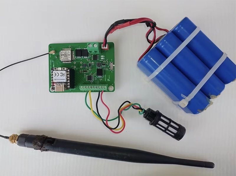
And there you have it folks, The Green Dot Board. This journey has been a total delight for me from the very beginning and I hope you can say the same thing. You can see below an illustration of how data is being received in the cloud. The next step from here would be to build either a custom dashboard to display all this information or to use a platform like Datacake which would integrate seamlessly with Loriot or TTN to do the data visualization.

I will be implementing some of the issues that arose along the way and updating the design in flux. You should be getting prompts of new updates as I do then and either choose to receive or deny them. Accepting updates is as simple as clicking the accept button.
This blog post highlights a series of innovative reference designs developed by renowned manufacturers using Flux. These reference designs encompass a variety of applications, including advanced light sensing, robust data communication, and compact distance measurement. This diverse array showcases the adaptability and effectiveness of Flux in meeting the varied needs of industrial sensing applications
Flux stands out in the PCB design industry, adhering to three core principles: promoting reusability, fostering collaboration, and keeping the designer focused. The emphasis on reusability allows individuals and organizations to amplify their impact. Users can leverage the work of others in the community by using templates, modules, or example projects, saving time and resources. This approach to PCB design not only streamlines the development process but also fosters a collaborative environment where designers can share and build upon each other's work, leading to more innovative and efficient designs. By keeping these principles at the forefront, Flux ensures that designers remain focused on what's most important, allowing them to deliver high-quality, effective PCB solutions for complex industrial sensing applications.
Our PCB design projects, showcased below, are not just innovative solutions but also serve as reusable modules in Flux. Each module is carefully crafted to ensure it can be easily adapted and used by anyone in the community. These modules exemplify the principle of reusability, allowing other designers to leverage our work for their own applications, fostering a collaborative and efficient approach to PCB design.

We developed a high-precision light intensity measurement system using the TSL25911FN. Flux Copilot played a crucial role in optimizing the layout for minimal interference and maximum sensitivity, ensuring accurate light measurement critical in quality control systems within manufacturing processes.

The PCA9615 was the cornerstone of our design for reliable long-distance I²C communication in noisy industrial environments. By leveraging Flux, we successfully mitigated EMI effects, making this design essential for large-scale industrial automation networks.

Utilizing the MLX90640ESF-BAA-000-TU, we crafted a sophisticated thermal imaging sensor. Flux was instrumental in the design, allowing for intricate circuitry that handles the high data throughput and thermal management required for accurate imaging. This sensor has become a game-changer in industrial safety and process monitoring, providing critical thermal data in real-time.

The PGA300ARHHR was the key component in our design of a high-precision pressure sensor system. This sensor is now widely used in fluid dynamics control in various industrial applications, demonstrating its versatility and reliability.

Our design using the VL53L0CXV0DH revolutionized short-range distance measurement in industrial settings. The layout and routing capabilities in Flux allowed us to maximize the sensor's range and accuracy, making it ideal for applications like inventory management and automated guided vehicles.

Incorporating the VL6180X, we developed a versatile multi-range sensor, adept at handling both proximity and ambient light measurement. Thanks to Flux's precision in PCB layout, we achieved a compact design that is now crucial in space-constrained industrial environments, particularly in robotics and assembly lines.

The VL53L1X enabled us to push the boundaries of long-range sensing. This sensor offers exceptional range and accuracy, which is now integral in large-scale automation and monitoring systems.

Our VL53L4CD-based design marked a significant advancement in high-resolution imaging sensors. Leveraging Flux's capabilities, we engineered a PCB that supports complex data processing, essential for applications like precision mapping and 3D modeling in industrial scenarios.

The TMF8801-1BM was central to our innovative time-of-flight sensor design. With Flux, we've enabled us to layout the board more efficiently, resulting in a sensor that excels in real-time positioning and collision avoidance in automated systems.

Using the TMF8820-1AM, we designed a sensor specifically for efficient object detection. The measurement tool in Flux allowed us to create a design that provides high-accuracy detection, making it ideal for safety and surveillance applications in industrial environments.

Our TCS3200D-TR-based design focused on high-fidelity color detection. We achieved a design that offers remarkable color sensing discrimination, essential in quality control processes in industries like textiles and printing.

The ISL29125IROZ-T7 allowed us to develop a high-performance light sensor. This sensor is used extensively in ambient light measurement and color balancing in industrial displays.

In our design with the AFBR-S50LV85D, we specialized in long-range laser measurement. This sensor isideal for applications requiring precise distance measurements, such as in warehouse logistics.

The AR0144CS was the foundation for our high-resolution CMOS sensor. Using Flux, we developed a PCB that supports complex image processing algorithms, crucial for detailed visual inspections in automated manufacturing processes.

Our design using the VCNL3040 redefined proximity sensing in industrial environments. With Flux, we crafted a compact and efficient layout, resulting in a sensor widely used in machinery safety and user interface applications.

The LTR-390UV-01 led to our breakthrough in UV light sensing. Thanks to Flux's layout design tool, we created a sensor that accurately measures UV light intensity, crucial for monitoring and controlling industrial processes involving UV curing and sterilization.

Using the QRE1113, we developed a reflective sensor adept at detecting object presence and positioning. This sensor offers high sensitivity and reliability, essential in applications like conveyor belt control and product sorting in manufacturing lines.

Our design with the GP2Y0D805Z0F focused on compact distance measurement solutions. Thanks to Flux, we were able to create a tiny yet highly effective sensor used in applications where space is at a premium, such as in handheld devices and robotics.
The design journey for each of these modules presented unique challenges, underscoring the versatility and adaptability required in the field of PCB design, particularly when using Flux.
These challenges and others like them were addressed through innovative design approaches, leveraging Flux’s capabilities in layout design and component integration. By overcoming these hurdles, we were able to create modules that are not only effective in their specific applications but also versatile enough to be adapted for a wide range of uses in the industrial sector.
The future of industrial sensing is marked by rapid technological advancements and a shift towards smarter, more efficient systems. Integration of IoT and AI technologies is transforming sensors into intelligent devices capable of real-time data analysis and decision-making. Miniaturization remains a key trend, with sensors getting smaller yet more powerful, catering to space and energy-efficient needs in diverse industrial applications.
Emerging materials and manufacturing techniques promise to enhance sensor sensitivity and durability, crucial for extreme industrial environments. Customization and flexibility in sensor design are increasingly important, enabling quick adaptation to specific industrial needs. This is where tools like Flux, promoting reusability and collaboration, become vital.
Additionally, environmental sustainability and data security are becoming critical considerations in sensor development and deployment. As sensors become more interconnected, ensuring secure and reliable data transmission is paramount.
In conclusion, the industrial sensing landscape is evolving towards more adaptable, intelligent, and sustainable solutions, with immense potential for innovation and impact in various industrial sectors.
We'd love to hear about your experiences with industrial sensor designs or any inquiries you might have. If you're looking for expert advice or services in PCB design, feel free to contact us or join our Slack channel and share with our community of 2,000 and growing. Together, we’ll change the future of PCB design!
Keep Innovating!